

Variable frequency automated capacitive radio frequency (RF) dielectric heating system
- Summary
- Abstract
- Description
- Claims
- Application Information
AI Technical Summary
Benefits of technology
Problems solved by technology
Method used
Image

Examples
example 1
[0162] Tests can be conducted to measure and characterize dielectric properties, including Debye resonances, of various constituents of muscle foods and potential packaging materials, as functions of frequency (100 Hz-100 MHz) and temperature (0-90.degree. C.).
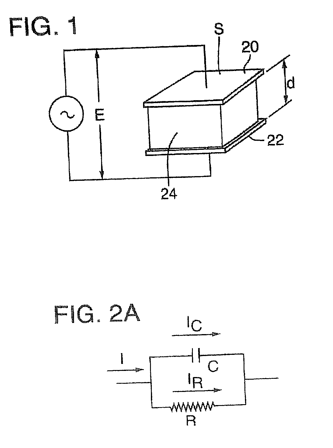
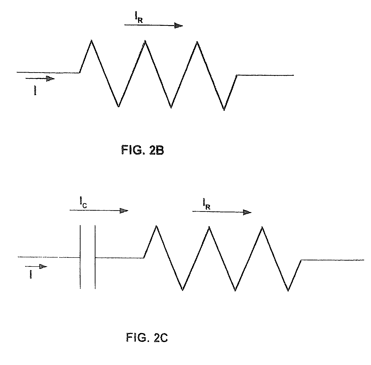
[0163] The experiments are to measure the impedance (parallel capacitor and resistor model) of muscle food samples, and potential packaging materials sandwiched in a parallel electrode test fixture placed within a temperature / humidity chamber. The equipment used for these experiments is as follows:
1 HP 4194A: 100 Hz-100 MHz Impedance / Gain-Phase Analyzer HP 41941A: 10 kHz-100 MHz RF Current / Voltage Impedance Probe HP 16451B: 10 mm, 100 Hz-15 MHz Dielectric Test Fixture for 4-Terminal Bridge HP 16453A: 3 mm, 100 Hz-100 MHz RF / High Temperature Dielectric Test Fixture Damaskos Test, Various specially-designed fixtures Inc. Dielectric 9 mm, 100 Hz-1 MHz Sealed High Temperature Products Co. Food / Semi-Solids LD3T Liquid-Tight Capacit...
example 2
[0168] A mathematical model and computer simulation program can model and predict the capacitive heating performance of packaged comminuted muscle foods based on the characterized dielectric properties.
[0169] There are underlying mathematical models that form the basis of the overall simulation. The electric permittivity has been classically modeled using Debye equations (Barber, H. 1983. Electroheat. London: Granada Publishing Limited; Metaxas, A. C. and Meredith, R. J. 1983. In Industrial Microwave Heating. Peter Peregrinus Ltd.; Metaxas, A. C. and Meredith, R. J. 1983. In Industrial Microwave Heating. Peter Peregrinus Ltd.; and Ramo, S., J. R. Whinnery, and T. Van Duzer. 1994. Fields and Waves in Communications Electronic, 3.sup.rd edition. New York: John Wiley & Sons, Inc.). These equations can be used to model a variety of relaxation processes associated with dielectric alignments or shifts in response to external varying electric fields. Each of these alignment processes has a...
example 3
[0195] Thermal and non-thermal effects of radio-frequency pasteurization on microbiological lethality, color, and texture in representative comminuted muscle foods are examined.
[0196] Sample Preparation
[0197] Two types of comminuted muscle samples are investigated: beef frankfurter and surimi seafood. Since all food ingredients mixed into samples contribute to every aspect of quality, to include microbiology, sensory, and physical properties, a commercial formulation for both samples is developed. For surimi seafood, the formulation is adjusted to maintain 75% moisture and 1.65% salt. Overall chopping procedures are based on the teachings in Yongsawatdigul, J., Park, J. W., Kolbe, E., AbuDagga, Y. and Morrissey, M. T. 1995, Ohmic heating maximizes gel functionality of Pacific whiting surimi. J. Food Sci. 60:10-14.
[0198] Surimi paste is stuffed into stainless steel tubes (1.9 cm I.D..times.17.5 cm long). Initial heating is conducted in a 90.degree. C. water bath until internal temper...
PUM
 Abstract
Description
Claims
Application Information