System and method for synchronizing data trasnmission across a variable delay interface

a data transnmission and delay interface technology, applied in data switching networks, frequency-division multiplex, synchronization arrangement, etc., can solve problems such as multipath noise, unoptimized lan communications, and typical wireless communications environment, and achieve limited wireless bandwidth and significant overhead

Inactive Publication Date: 2002-07-11
CONEXANT
View PDF9 Cites 135 Cited by
  • Summary
  • Abstract
  • Description
  • Claims
  • Application Information

AI Technical Summary

Benefits of technology

0016] Other than the sequencing problems described above, which can effect the synchronization between scheduler and MAC transmitter timing, the variable interface delay or latency hinders the scheduler's ability to perform properly various periodic functions and to monitor such periodic functions. Collocated with the scheduler is the point coordinator and the distribution services which provide AP functions. The point coordinator coordinates the flow of frames for active streams of the associated stations, which requires polling those stations for inbound frames. In particular, the point coordinator generates and enqueues polling lists and must monitor the success of the polling lists and make the necessary adjustments. In a QoS environment the scheduler is generally responsible for admittance and re-admittance of QoS frames to the set of transmit queues of the MAC at the AP and for maintaining polling lists for QoS streams. To compensate for the much greater probability of the loss of data frames on a wireless medium, the WLAN MAC protocol incurs significant overhead, including transmission of acknowledgement frames and data frame retransmissions when not acknowledged. This reduces the portion of the already limited wireless bandwidth that is available for user data transfers.

Problems solved by technology

Wired networks are well known and generally have acceptable performance, but have many limitations, such as various cable management and convenience issues.
The typical environment for wireless communications, however, is very noisy and not optimal for LAN communications.
For example, most homes and work places include many electronic devices that transmit or emit RF energy resulting in an electronically noisy environment that may interfere with WLAN communications.
For example, most indoor environments or rooms include multiple surfaces that are reflective to RF energy, creating multipath noise.
Also, movement of items or devices or the like, such as hands, bodies, jewelry, mouse pointers, etc. or activation of electronic devices, such as cooling fans or the like, affects the overall wireless communication path and potentially degrades wireless communication performance.
Wireless communications are problematic for various other reasons.
In some environments, separate WLANs are proximally located which increases the likelihood for destructive interference between wireless devices that are not intended to communicate with each other.
Typical solutions of increasing transmit power (or "RF power" or "radiated power") or increasing clock speed that are often available in wired devices with ready access to utility power or the like is not usually available for wireless devices.
It is not necessarily an option to decrease transmit power to reduce interference since this also reduces the communication area within a WLAN and reduces coverage faster than interference due to the square law.
Nonetheless, audio applications still have many timing constraints and requirements.
Audio information, for example, is very sensitive to jitter and latency variation, which if not properly addressed may result in a breakdown of communications or dissatisfied users at much lower levels at which the audio cannot be understood at all.
This is particularly true for two-way communications, such as voice-over-IP and video conferencing where delay, latency and jitter issues must be addressed and resolved, which is especially difficult for wireless communications.
Wired LANs, such as communications based on Ethernet 802.3, for example, are success-oriented and have relatively low delay and very low loss of data packets, whereas wireless communications are much less robust and have a substantially higher data loss rate.
Wired communications are much more predictable, with somewhat deterministic delays, whereas wireless communications exhibit significantly greater and less predictable delays.
Such collision detection methods are not practical in wireless communication since it is difficult for a wireless receiver to detect wireless transmission of another device while the local transmitter is operating.
In wireless LANs, because of network media which incur frame loss rates as high as 10.sup.-3, the retry and acknowledge functions have been incorporated into the MAC / PHY functions, and thereby consume valuable bandwidth for wireless communications.
In contrast, for wireless transmissions, the receiver consumes a variable amount of valuable time to detect and resolve a signal being transmitted and to decode the information within the signal.
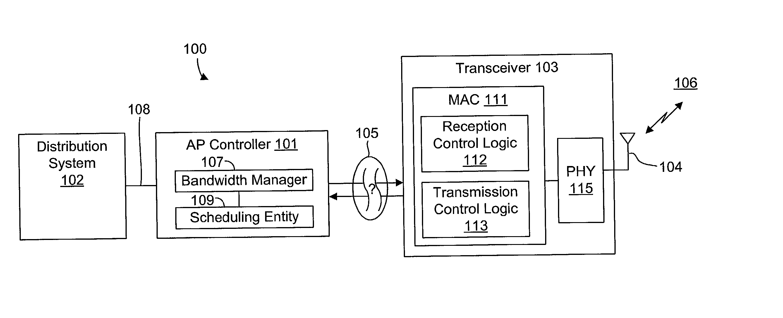
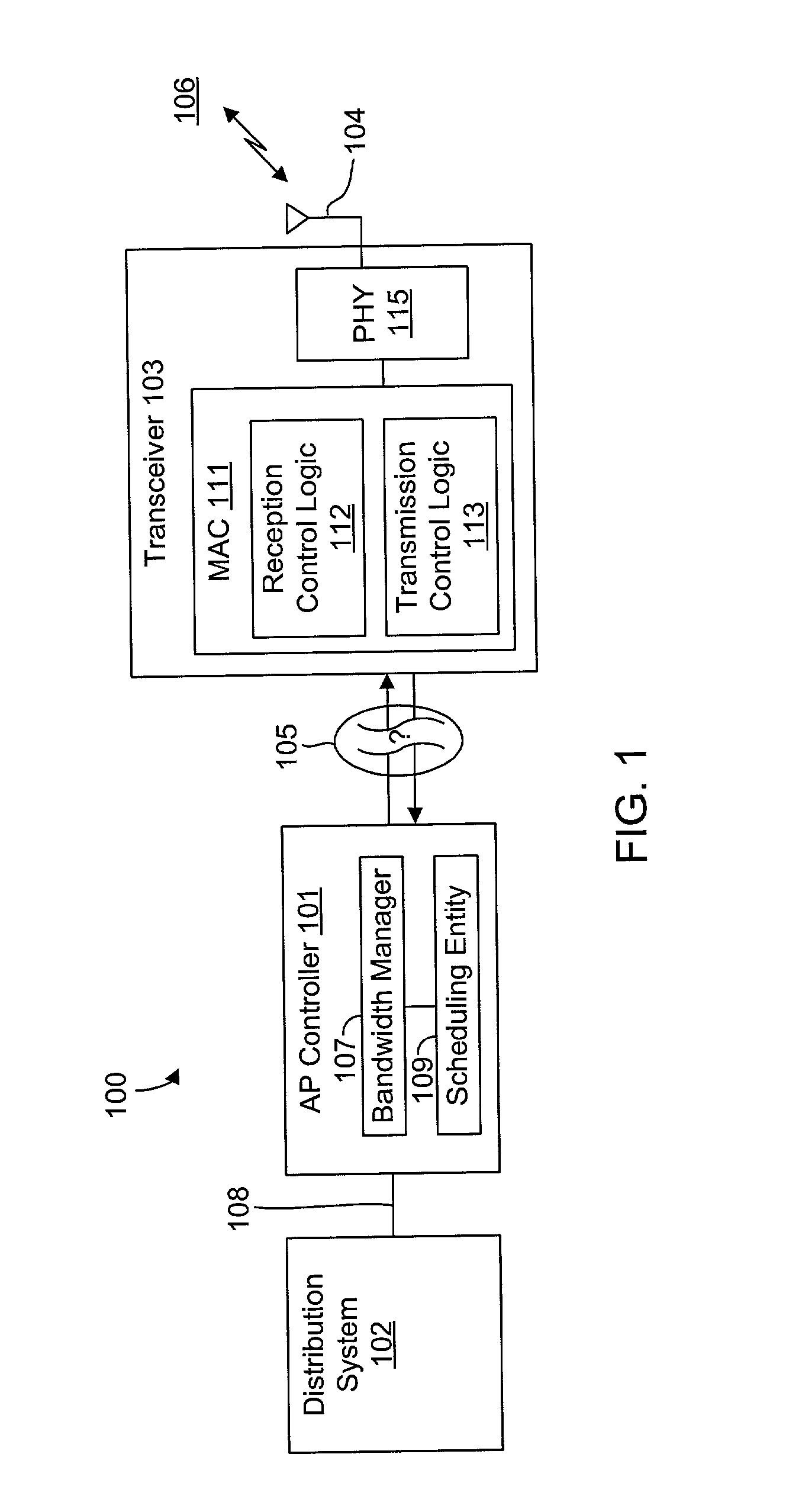
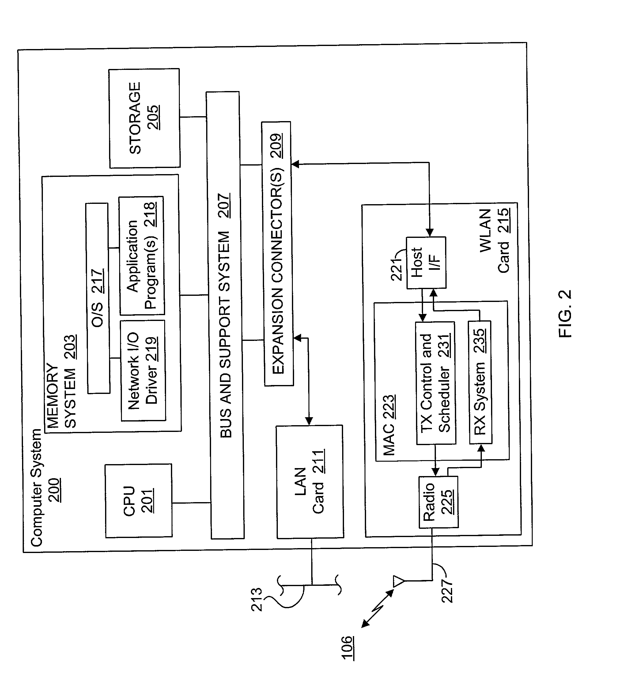
The problems with WLAN communications are compounded when implemented on personal computer (PC) platforms or the like commonly employed in home or small office environments.
Host processor interrupt latency, however, is variable, not readily determinable, and for the most part, uncontrollable by the wireless system including both the higher layer protocol software and the MAC / PHY transceiver.
The timing of data transfers, interrupts, and indications between the upper-layer protocol functions and the lower-layer MAC / PHY transceiver functions, therefore, is variable and not known and subject to indeterminate delay and latency, so that the host software and drivers are unable to closely control or accurately determine the timing of the information transmission.
The scheduler software has no control over nor ability to measure host processor interrupt response latency.
This is especially problematic when the host is running a general purpose operating system, such as Windows NT or the like, rather than a real-time operating system (RTOS), because a general purpose OS is not concerned with limiting interrupt latency whereas an RTOS typically specifies an upper bound on such latency.
There is no guarantee that the scheduler will be able to respond fast enough to classify new arrivals, retrieve undelivered frames, make the required prioritization decisions, and load the first frame(s) for transmission during the CFP of the next Superframe between the end of a full-length CFP and the end of the Beacon that starts the next Superframe.
Also, due to uncontrollable and unmeasurable (by the scheduler in real time) variations in host interrupt latency, it is not possible to ensure that the first frame of the next Superframe reaches the head of the relevant transmit queue in time even if the frame is submitted in response to a Superframe-timed interrupt, such as in response to a CF-End or a TBTT event.
Other than the sequencing problems described above, which can effect the synchronization between scheduler and MAC transmitter timing, the variable interface delay or latency hinders the scheduler's ability to perform properly various periodic functions and to monitor such periodic functions.
To compensate for the much greater probability of the loss of data frames on a wireless medium, the WLAN MAC protocol incurs significant overhead, including transmission of acknowledgement frames and data frame retransmissions when not acknowledged.
This reduces the portion of the already limited wireless bandwidth that is available for user data transfers.
Such bypassing of frames may occur, for example, if the transmitter is unable to transmit all of the queued frames intended for a selected interval or if the host system or variable delay interface is too slow in providing the frames, causing them to arrive after the end of the interval.

Method used


Image

  • System and method for synchronizing data trasnmission across a variable delay interface
  • System and method for synchronizing data trasnmission across a variable delay interface
  • System and method for synchronizing data trasnmission across a variable delay interface

Examples


Embodiment Construction

[0040] FIG. 1 is a simplified block diagram of an access point (AP) 100 within a wireless communication system. The AP 100 includes a station host or AP controller 101 and a wireless network transceiver 103 that communicate in a wireless medium 106 via at least one antenna 104. It is noted that the AP 100 is also representative of the applicable functionality of a wireless station in accordance with embodiments of the present invention. In the case of a station, the AP controller 101 is typically a personal computer (PC), wireless information appliance, or the like, with various subsystem functions performed by software executing on a processor that is also used to perform other functions of the station. In the case of an AP, the AP controller 101 is typically a dedicated processor that only performs the network-related functions, although there are embodiments of an access point in software that runs on a PC. The more extensive set of functions for illustrating the present inventio...


PUM


Abstract

A method of synchronizing data transmission between a host computer system and a transmitter across an interface with variable delay or latency. The host computer system marks transition frames between successive transmission intervals and transfers the outgoing frames across the variable interface to the transmitter. The transmitter enqueues outgoing frames into one or more FIFO transmission queue(s) and processes the enqueued frames as appropriate for the communication protocol in use. Marked frames are detected as they reach the head of the appropriate transmit queue. In particular, while bypassing is not active, the transmitter transmits unmarked frames until the end of the current interval, or until there is insufficient time in the interval to transmit another frame or until a marked frame is detected. While bypassing is not active, the transmitter terminates transmission from the transmit queue when a marked frame is detected during each interval. While bypassing is active, the transmitter discards unmarked frames without transmission until a marked frame is detected. During each interval, the transmitter activates bypassing if a marked frame has not been detected and deactivates bypassing if a marked frame is detected while bypassing is active. The transmitter enables queue mark operation if a marked frame is detected while queue mark operation is not enabled. The transmitter increments a bypass counter each time an interval ends without detecting a marked frame, and disables queue mark operation if the bypass counter reaches a predefined limit.

Description

CROSS-REFERENCE TO RELATED APPLICATION(S)[0001] The present application is based on U.S. Provisional Application entitled "System And Method For Synchronizing Data Transmission Across an Interface With Variable Timing", Application No. 60 / 261,436 filed Jan. 11, 2001, which is hereby incorporated by reference in its entirety.[0002] The present invention relates to LAN communications, and more particularly to a system and method for synchronizing data transmission across a variable delay interface with indeterminate delay or latency.DESCRIPTION OF RELATED ART[0003] Network communication is a growing area of technology, both for business and home applications. A network system enhances communication and provides a suitable environment for enhanced productivity and capabilities, both at home and in the workplace. It is becoming more advantageous and common for small businesses and home environments to include a local area network (LAN) that is connected to external networks, such as the...

Claims


Application Information

Patent Timeline
Patent Type & Authority Applications(United States)
IPC IPC(8): H04L1/08H04L1/16H04L1/18H04L12/28H04L12/403H04L12/56
CPCH04L1/08H04L1/16H04L1/1877H04L12/5693H04L47/10H04L47/13H04L47/14H04L47/2433H04L47/31H04L47/32H04L47/564H04L47/6245H04W28/14H04W56/00H04W72/12H04W80/00H04L47/50H04W28/02H04W8/04
Inventor FISCHER, MICHAEL A.LEACH,, DAVID J. JR.HUGHES, JACK B.
Owner CONEXANT
Why Eureka
Try Eureka