This is not matched with a durability on several million sheets of a non-single
crystalline silicon photosensitive member, thus posing an obstacle to wide popularization of the non-single crystalline
silicone photosensitive member.
Further, when used in the above-mentioned cleanerless system, some among a variety of non-single
crystal material silicon photosensitive members is liable to convert the inverted to a polarity distribution not readily recovered by the
fog-prevention
voltage, more specifically, to an average polarity opposite to the normal charge polarity, thus posing a difficulty for realizing a cleanerless system capable of fully enjoying the advantages of a non-single
crystalline silicon photosensitive member.
Particularly, compared with a surface layer comprising an organic material such as a resin, a surface layer comprising a carbon-based non-single
crystal material is liable to make difficult the normalization of inverted toner, thus causing image defects, such as image
fog and lower
image density due to deterioration of the developer.
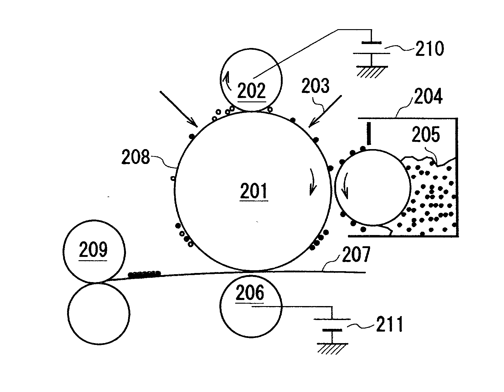
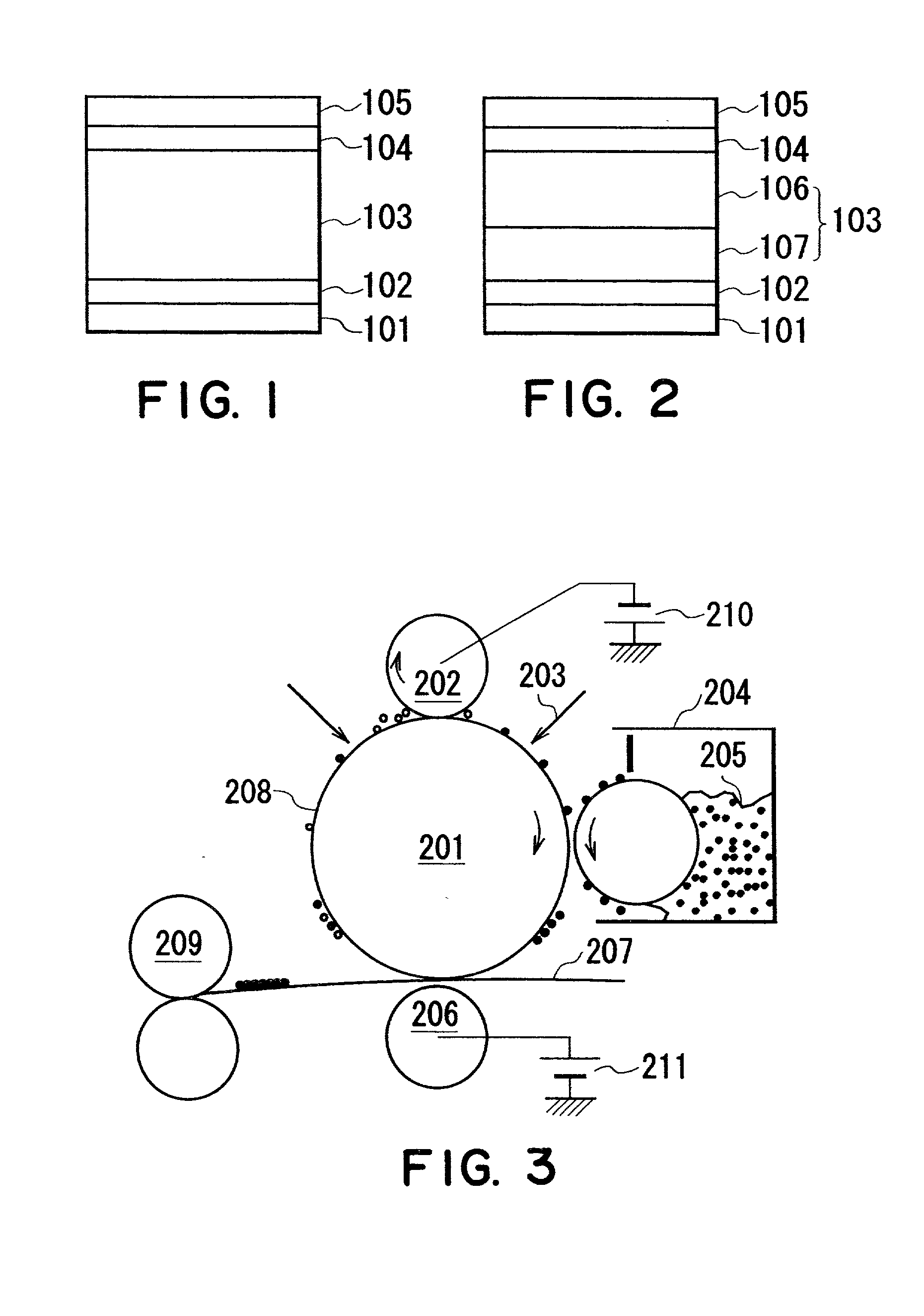
On the other hand in a BAE (back area
exposure) scheme wherein a region other than an exposed (i.e., charge-attenuated) part is developed with a toner charged to an opposite polarity, there are liable to be encountered difficulties that the toner fails to be discharged because of an insufficient charge or fails to be recovered even if it is discharged with a sufficient charge.
However, if a
corona discharger is used in the charging step, a
corona discharge irregularity is caused at the time of the transfer residual toner passing through the charger to result in a charge irregularity on the a-Si photosensitive member surface or
abnormal discharge to damage the a-Si photosensitive member in a worst case.
As a result, the occurrence of
abnormal discharge could be prevented, but several difficulties were encountered due to soiling of the contact charger with the transfer residual toner, such as a lowering in performances of the charging member, a shorter life of the charging member, inferior
image contrast and uniformity due to lowering in charging ability and a lowering in performances of transfer residual toner by attachment to the contact charger resulting in lower image qualities, such as increased
fog.
Below 15 .mu.m, a current passage of the charging member is liable to be excessively large to accelerate the deterioration.
Above 60 .mu.m, abnormally grown portions are liable to be formed in sizes of 50-150 .mu.m in horizontal direction and 5-20 .mu.m in height, so that non-ignorable damage to the charging member
rubbing the surface can be occur in some cases.
%, the normalization toner charge discharged from the charging means is liable to be insufficient to result in fog.
%, the
discharge of the toner from the charging is liable to be obstructed, thus resulting in inferior charging performance, fog and increased surface wearing.
%, the optical
band gap is narrowed to provide an unsuitable sensitivity.
%, the
hardness is liable to be lowered to result in abrasion.
Below 5 nm, it becomes difficult to attain the effect in a long-term use.
Above 2000 nm, difficulties, such a lowering in
photosensitivity and residual potential, are liable to be encountered.
However, an excessively large power is liable to cause
abnormal discharge to result in inferior properties of the image-bearing member, so that the power should be suppressed within an extent of not causing abnormal
discharge.
However, an excessively large power is liable to cause abnormal discharge to result in inferior properties of the image-bearing member, so that the power should be suppressed within an extent of not causing abnormal discharge.
Below 150 volts, the toner cannot be sufficiently transferred for development from the toner-carrying member to the a-Si photosensitive member and accumulated on the toner-carrying member to cause a difficulty, such as an
image density lowering, in some cases.
On the other hand, above 800 volts, the current passage to the charging member is increased to accelerate the deterioration of the charging member and partial minute discharge is liable to occur because of the large applied
voltage.
If the volume resistivity of the charging roller is outside the above range, the above-mentioned charging and leakage resistance performances are not achieved in some cases.
Accordingly, below 0.1 .mu.m, an effective amount of the charging particles cannot be ensured, thus failing to supply an amount of the charging particles sufficient to overcome charging inhibition by attachment or
contamination of an insulating transfer residual toner onto the contact charging member in the charging step to well charge the image-bearing member.
As a result, charging failure is liable to occur.
If the particle size of the charging particles is above 10 .mu.m, charging particles detached from the charging member cause light-interruption or
diffusion of
exposure light for writing an electrostatic latent image, thus resulting in a defective electrostatic latent image to lower a
resultant image quality in some cases.
However, when the content of the charging particles is excessively increased, the developing characteristic is lowered particularly in a high-
humidity environment, thus causing a lowering in
image density or toner scattering.
On the other hand, an excessively lower resistivity of the charging particles also provides inferior results, so that the charging particles may preferably have a resistivity of at least 1.times.10.sup.1
ohm.cm in order to charge the charging particles to allow development at a non-image portion, thus promoting charging performance.
Below 4 nm, the inorganic
fine powder is caused to have a strong agglomeratability to damage the image-bearing member, thus being liable to cause image defects.
Above 100 nm, a sufficient flowability-improving effect to the magnetic toner is not attained to cause image defects resulting from insufficient charge of the magnetic toner.
A magnetic toner having a weight-average particle size (D4) below 3 .mu.m is liable to cause a lower transferability, thus failing to retain a uniform chargeability.
If the D4 is larger than 10 .mu.m, the developing performance is lowered, thus failing to form high-quality images.
However, if the magnetic toner has a saturation
magnetization of below 10 Am.sup.2 / kg at a
magnetic field of 79.6 kA / m, it becomes difficult to convey the magnetic toner on the toner-carrying member, and magnetic toner ear formation on the toner-carrying member becomes unstable, thus failing to provide uniform charge to the toner.
As a result, image defects, such as fog, image density irregularity and
recovery failure of transfer-residual toner are liable to be caused.
If the
magnetization exceeds 50 Am.sup.2 / kg, the toner particles are liable to have an increased magnetic agglomeratability, to result in remarkably lower flowability and transferability.
At the same time, an amount thereof located at the nip portion between the image-bearing member and the charging particle-carrying member is also decreased relative to that of the transfer residual toner, thus resulting in a lowering in chargeability leading to an occurrence of fog and image
staining.
%, it becomes difficult to supply an amount of the electrophotographics sufficient to overcome charging inhibition by the attachment or
contamination of the insulating transfer residual toner onto the contact charging member to well effect charging of the image-bearing member to the nip portion or the charging section in proximity thereto between the charging member and the image-bearing member, thus lowering the chargeability to cause charging failure in some cases.
%, the amount of the electroconductive particles recovered by the simultaneous developing and cleaning operation becomes too large, thus lowering the chargeability and developing performances of the magnetic toner at the developing section to cause a lowering in image density or toner scattering in some cases.

