Thermal management materials having a phase change dispersion

a technology of phase change dispersion and management materials, which is applied in the direction of light beam reproducing, instruments, and semiconductor/solid-state device details, etc., can solve the problems of increasing design complexity, increasing device size, and increasing the complexity of circuit designs of modern electronic devices, and achieves low thermal impedance

Inactive Publication Date: 2003-08-14
PARKER INTANGIBLES LLC
View PDF79 Cites 84 Cited by
  • Summary
  • Abstract
  • Description
  • Claims
  • Application Information

AI Technical Summary

Benefits of technology

[0017] The present invention is directed to a thermally-conductive interface, and a material therefor, for a thermal management assembly involving, for example, a heat source such as an electronic chip or other heat-generating component and a thermal dissipation member such as a heat sink or spreader disposable in thermal adjacency with the electronic component for the conduction of heat therebetween. Particularly, the invention is directed to a material in the form of a thermally-conductive compound which is formable into a sheet, pad, or other layer which is compliant or otherwise conformable between the interfacing surfaces of the electronic component and the heat sink or spreader to provide a low thermal impedance across the assembly, and which affords lower thermal impedance for improved heat transfer performance.
[0020] Advantageously, the fusible metals and / or alloys herein involved exhibit thermal conductivities on the order of about 20 W / m-K or more which are comparable to those exhibited by conventional metal powder particulate fillers. However, within the interface or bondline, such metals and alloys also are conformable with the polymeric component such that the minimum thickness of the interface material is not limited by a fixed filler particle size. Indeed, it has been observed that such metals and alloys behave within the interface material of the present invention more like the continuous phase than a dispersed filler phase and thereby do not adversely impact the overall melt flow viscosity of the material. In contrast, the use of particulate fillers has been observed to effect a substantial increase of the melt flow viscosity as a result of increased resin demand. Moreover, as compared to the use of a fusible metal or alloy alone as a thermal interface, the composite material of the present invention affords the opportunity, by virtue of the combination of a resin, wax, or other polymeric component with the fusible metal or alloy, to better control melt flow viscosity which otherwise could result in the fusible metal component, which alone may have a relatively low melt flow viscosity, flowing out of the interface with the result of a dry joint and attendantly high thermal resistance.
[0037] Although the polymeric component may be provided as a silicone, polyurethane, acrylic, acrylic pressure-sensitive adhesive (PSA), or other material conventional used for thermal interface materials, the polymeric component alternatively may be formulated as a phase-change material (PCM). By "phase-change," it is meant that the material is form-stable at normal room temperature, i.e., about 25.degree. C., in a 
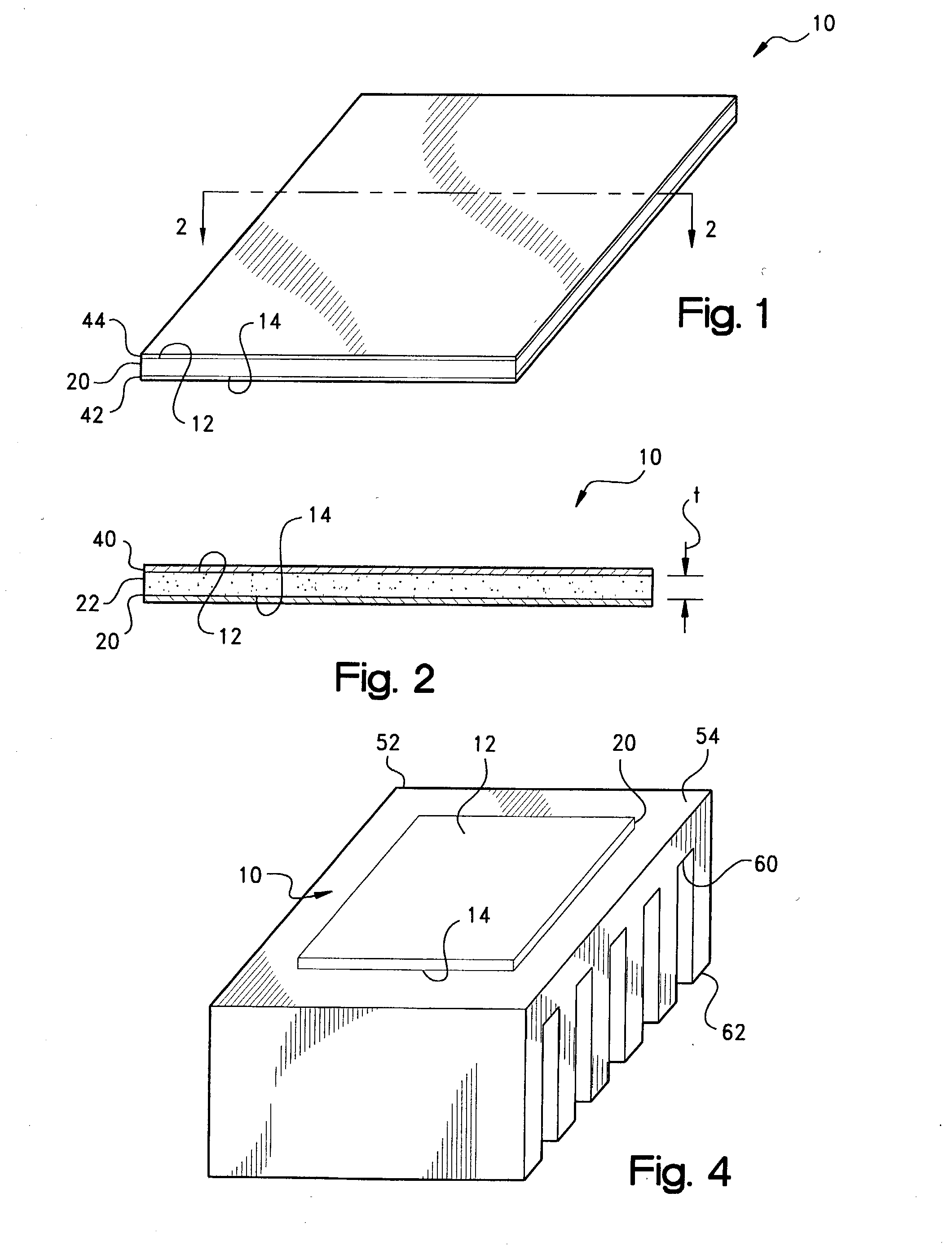
solid, semi-solid, glassy, or crystalline first phase or state, but is substantially conformable at an elevated temperature or temperature range in a liquid, semi-liquid, or otherwise viscous second phase or state. Unlike conventional greases or waxes, layer 20 as formulated with such a PCM, advantageously is form-stable at normal room temperature such that pad 10 may be shipped and handled without causing the layer to slump, sag, or run.
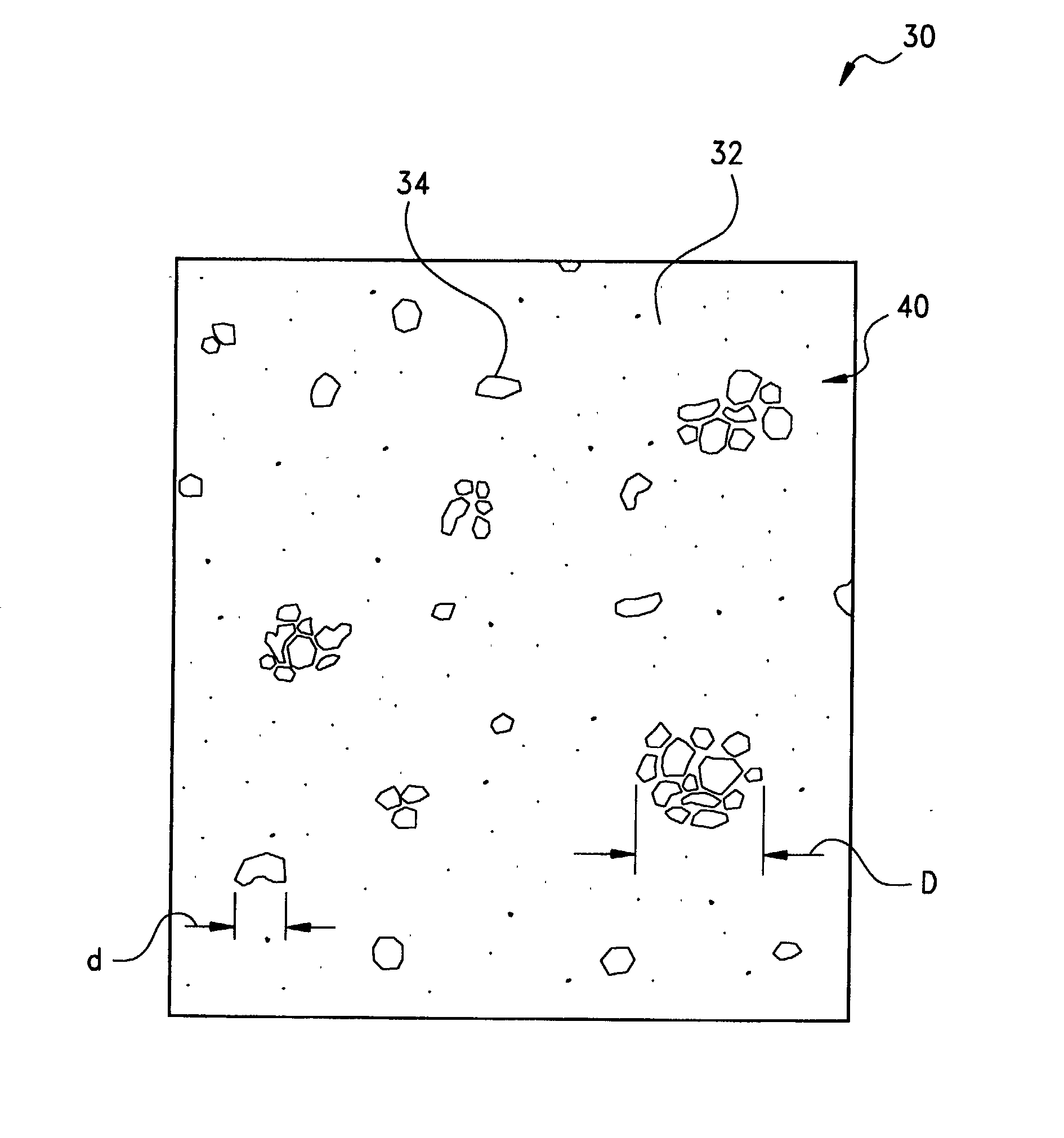
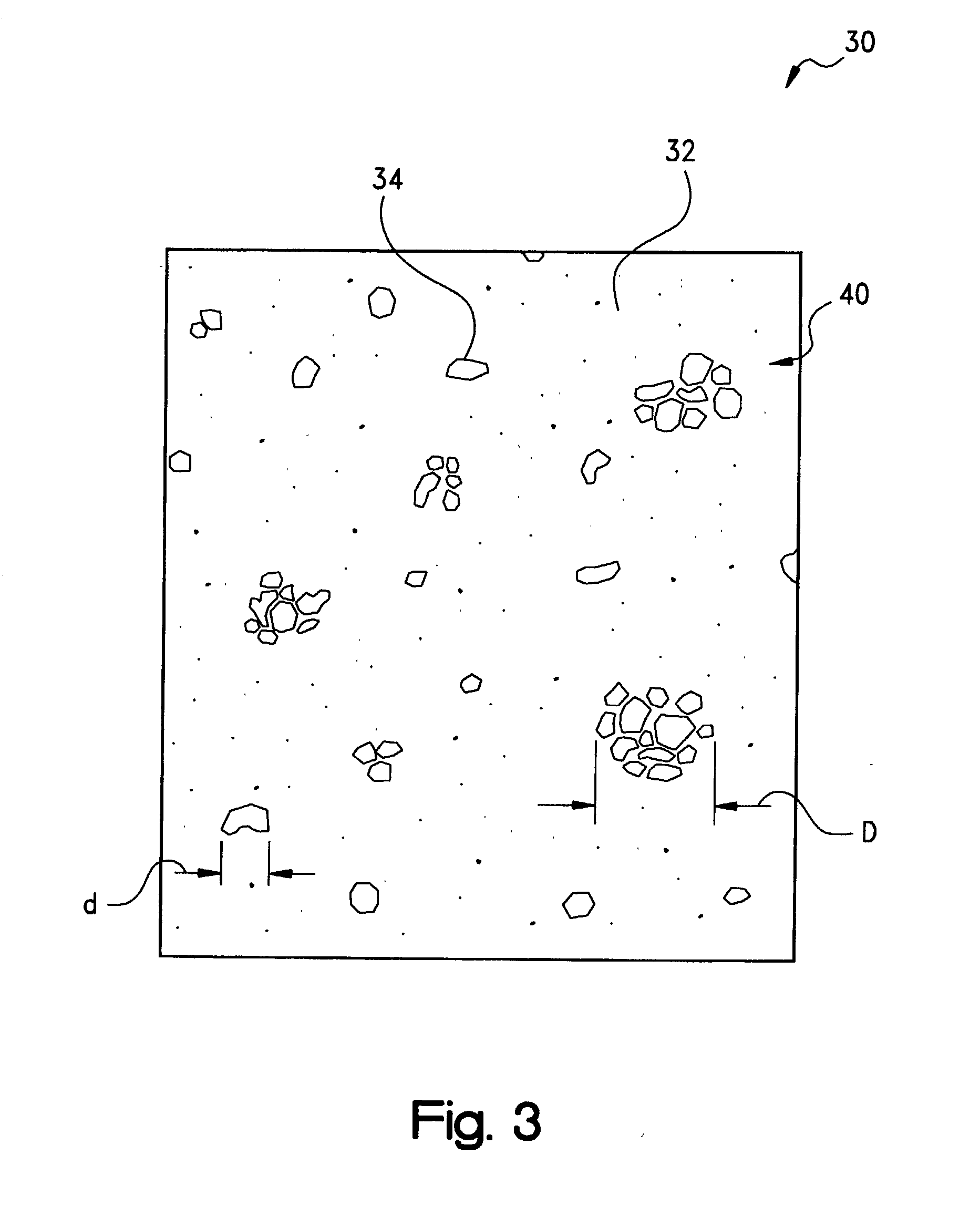
[0050] Following the heating of the layer 20 to a temperature which is above the phase transition temperature of each of the components, the domains 34 of the second, conformable phase of the dispersed fusible metals and / or metal alloys have been observed to form an emulsion with the second phase of the PCM or other matrix phase 32. Although the respective transition temperatures of the PCM and the fusible metals and metal alloys may be selected independently, for most formulations of the thermally-conductive compound of the present invention it will be preferred that the transition temperature of the PCM be lower, such as by at least about 5.degree. C., than that of the fusible metals and alloys. In his regard, the compound may exhibit two distinct phase change temperatures, namely, a first order transition of the matrix phase constituent and a second order transition of the dispersed phase constituent. In contrast, it has been observed that in the case where the transition temperature of the PCM is higher than that of the fusible metals and metal alloys, there is the potential for the metal or alloy to coalesce, with an attendant reduction in thermal performance, or to flow out of the bondline with the result of a dry bondline and increased thermal resistance. Advantageously, however, by virtue of the PCM matrix, the overall melt flow viscosity of the emulsified melt of the compound may be maintained to be, for example, between about 10,000-100,000 cp (10-100 Pa-s) such that the melt is sufficiently viscous to remain in the bondline. Moreover, it has been observed that the addition of alumina, boron nitride, or other thermally-conductive filler particles to the PCM, although not required and in many applications not necessarily preferred, provides optimal thermal performance in that the filler particles may function as a thermal bridge between the domains 34 of the dispersed phase component giving the apparent effect of domain to domain contact along a thermal path or network.
[0052] Although not required, a carrier or reinforcement member (not shown in FIGS. 1 and 2) optionally may be incorporated within layer 20 as an interlayer therewithin or on one or both of the surfaces 12 and 14 to provide increased tear resistance. Conventionally, such member may be provided as a film formed of a thermoplastic material such as a polyimide or polyetheretherketone (PEEK), a layer of a woven or non-woven, e.g., needled, fiberglass fabric, cloth, web, or mat, or an aluminum or other metal foil, screen, or expanded mesh. Such reinforcement may improve the physical strength of the layer 20 and pad 10 to better facilitate handling at higher ambient temperatures and die cutting into a variety of geometries. The reinforcement member typically will have a thickness of between about 0.5-5 mil (12.5-125 .mu.m), with a thickness of about 1-2 mils (25-50 .mu.m) being preferred for metal foils.
[0064] Further in this regard, the domains 34 may be seen to assume a flattened, more ellipsoidal geometry within the viscous melt of the second phase of the matrix 32. Overall, such second phase of the compound of layer 20 provides increased surface area contact with the heat transfer surfaces 52 and 54 for the displacement of air therefrom and the better exclusion of air pockets or other voids with a resultant improvement in both the efficiency and the rate of heat transfer through the pad 10. Moreover, as depending on, for example, the melt flow index or viscosity of the PCM and the magnitude of any externally-applied pressure such as from a clamp or clip, the interface gap between the surfaces 54 and 56 may be closed from, for example, the thickness t.sub.1 of FIG. 6A to the to a minimum bondline thickness, such as represented by t.sub.2, of the compound of layer 20 to further improve the efficiency of the thermal transfer therebetween. The latent heat effects associated with the phase change of the matrix and domain constituents additionally contributes to the cooling of the electronic component 58.

Problems solved by technology

Circuit designs for modern electronic devices such as televisions, radios, computers, medical instruments, business machines, communications equipment, and the like have become increasingly complex.
Although the complexity of the designs has increased, the size of the devices has continued to shrink with improvements in the ability to manufacture smaller electronic components and to pack more of these components in an ever smaller area.
As electronic components have become smaller and more densely packed on integrated boards and chips, designers and manufacturers now are faced with the challenge of how to dissipate the heat which is ohmicly or otherwise generated by these components.
Indeed, it is well known that many electronic components, and especially power semiconductor components such as transistors and microprocessors, are more prone to failure or malfunction at high temperatures.
Thus, the ability to dissipate heat often is a limiting factor on the performance of the component.
For high power circuits and the smaller but more densely packed circuits typical of current electronic designs, however, simple air circulation often has been found to be insufficient to adequately cool the circuit components.
These pockets reduce the overall surface area contact within the interface which, in turn, reduces the heat transfer area and the overall efficiency of the heat transfer through the interface.
Moreover, as it is well known that air is a relatively poor thermal conductor, the presence of air pockets within the interface reduces the rate of thermal transfer through the interface.
The greases and waxes of the aforementioned types heretofore known in the art, however, generally are not self-supporting or otherwise form stable at room temperature and are considered to be messy to apply to the interface surface of the heat sink or electronic component.
Moreover, use of such materials typically involves hand application or lay-up by the electronics assembler which increases manufacturing costs.

Method used


Image

  • Thermal management materials having a phase change dispersion
  • Thermal management materials having a phase change dispersion
  • Thermal management materials having a phase change dispersion

Examples


example 1

[0066] In a first representative formulation, about 70% by total weight of a fusible metal ASTM Alloy 117 was dispersed in a boron nitride (BN)-filled PCM compound (30% BN in a polymeric binder, Thermflow.RTM. T454, Chomerics Division, Parker Hannifin Corp., Woburn, Mass.) by admixing the two components which were heated to a temperature of about 60-70.degree. C. In the blend so formed, the alloy was observed to form a dispersed phase of discrete domains and agglomerations thereof within a continuous matrix phase of the BN-filled PCM.

[0067] The Thermflow.RTM. T454 PCM compound itself was reported as having a phase change temperature of about 43.degree. C., a thermal impedance of about 0.025.degree. C.-in.sup.2 / W (0.63.degree. C.-cm.sup.2 / W) at about 90 psi (620 kPa), and an apparent thermal conductivity of about 0.7 W / m-K.

[0068] As to the alloy, such 117 alloys are specified per ASTM B774 as eutectics having a melting point of 117.degree. F. (47.degree. C.) and comprising between 44...

example 2

[0073] In a second representative formulation, the BN-filled Thermflow.RTM. T454 PCM compound was admixed with about 70% by total weight of another fusible metal alloy (METSPEC.TM. 141 ("MS 141"), MCP Metalspecialties, Fairfield, Conn.). The lead and cadmium-free alloy used in this Example 2 was a eutectic of 32.5% bismuth, 16.5% tin, and 50% indium, and had a melting point of 141.degree. F. (61.degree. C.). This alloy was reported as having a an apparent thermal conductivity of about 20 W / m-K.

[0074] As in Example 1, the PCM compound-fusible metal alloy admixture of this Example 2 was formed by coating into a 5 mil (125 .mu.m)-thick sheet for thermal characterization. Thermal impedance again was determined according to ASTM D5470 at an applied pressure of about 90 psi (620 kPa) and a minimum bondline thickness (MBLT) of about 1 mil (25 .mu.m). The results are summarized in Table 2 below as compared to reported values for the Thermflow.RTM. T454 material itself and for a standard sil...


PUM

PropertyMeasurementUnit
domain transition temperatureaaaaaaaaaa
matrix transition temperatureaaaaaaaaaa

Abstract

A thermally-conductive interface interposable intermediate a first heat transfer surface and an opposing second heat transfer surface to provide a thermal pathway therebetween. The interface includes a thermally-conductive compound formed into a layer which is conformable between the first and second heat transfer surface. The compound is an admixture of: (a) a polymeric constituent forming a continuous matrix in the layer; and (b) a dispersed constituent forming discrete domains within the matrix, the domains being form-stable at normal room temperature in a first domain phase and conformable between the first and second heat transfer surface in a second domain phase, and the domains having a domain transition temperature above normal room temperature from the first domain phase to the second domain phase. The dispersed constituent may be a fusible, i.e., low temperature melting, metal or metal alloy.

Description

CROSS-REFERENCE TO RELATED CASES[0001] The present application claims the benefit of the filing date of U.S. Provisional Application Serial No. 60 / 354,810; filed Feb. 6, 2002, the disclosure of which is expressly incorporated herein by reference.[0002] The present invention relates broadly to thermal management materials for electronic devices. Such materials commonly are used as heat transfer interfaces between, for example, the mating heat transfer surfaces of a heat-generating, electronic component, such as an integrated circuit (IC) chip, and a thermal dissipation member, such as a heat sink or spreader, for the conductive cooling of the electronic component. More particularly, the present invention relates to a thermally-conductive interface material which is formed as an admixture of a continuous phase constituent and a dispersed phase constituent which is provided to be solid, semi-solid or otherwise form-stable in a first state at normal room temperature but conformable with...

Claims


Application Information

Patent Timeline
Patent Type & Authority Applications(United States)
IPC IPC(8): C09K5/06H01L23/427
CPCC09K5/063H01L23/4275H01L2924/3011Y10S428/923H01L2924/0002Y10T428/27Y10T428/256Y10T428/25Y10T428/263Y10T428/257Y10T428/258Y10T428/26H01L2924/00Y10T428/31801
Inventor BUNYAN, MICHAEL H.YOUNG, KENT M.
Owner PARKER INTANGIBLES LLC
Why Eureka
Try Eureka