High-polymer eletrolyte type thin film fuel cell and its driving method

a fuel cell and high-polymer electrolyte technology, applied in cell components, transportation hydrogen technology, electrochemical generators, etc., can solve the problems of difficult handling of individual unit cells, difficult to supply fuel or oxidant gas to individual unit cells, and inability to easily achieve fuel cell volume capable of being installed in mobile devices. , to achieve the effect of improving the generation efficiency of thin film fuel cells, improving water retention, and improving the outpu

Inactive Publication Date: 2003-09-11
PANASONIC CORP
View PDF6 Cites 49 Cited by
  • Summary
  • Abstract
  • Description
  • Claims
  • Application Information

AI Technical Summary

Benefits of technology

0075] Since the thickness of the polymer electrolyte thin membrane is small in the thin film fuel cell of the present invention, there is a possibility that the reaction gases are diffused to react on the opposite electrodes, causing a fear of the performance degradation. Therefore, the anti-crossover film serving as a catalyst material is laminated with the polymer electrolyte thin membrane, and the fuel gas and oxidant gas that have crossed over are reacted on the anti-crossover film to impede them from reacting on the opposite electrodes,

Problems solved by technology

In a conventional fuel cell configuration as described above, unit cells each comprising an MEA and separator plates sandwiching the MEA are simply stacked in the thickness direction, and a fuel cell having a volume capable of being installed in mobile devices cannot be readily achieved by merely downsizing a conventional fuel cell without changing the configuration.
Additionally, it is difficult to supply a fuel or oxidant gas to individual unit cells by simply stacking them in the thickness direction in order to achieve a serial connection.
Further, the smaller the thickness and a

Method used


Image

  • High-polymer eletrolyte type thin film fuel cell and its driving method
  • High-polymer eletrolyte type thin film fuel cell and its driving method
  • High-polymer eletrolyte type thin film fuel cell and its driving method

Examples


embodiment 1

[0094] While two pieces of the fuel cells described in Embodiment 1 were held at 75.degree. C., a hydrogen gas heated and humidified to have a dew point of 50.degree. C. and air at room temperature were supplied to the anodes and cathodes, respectively, and the cells were continuously operated at a fuel utilization rate of 30%, an air utilization rate of 10% and a current density of 0.1 A / cm.sup.2. One of the fuel cells (Cell A) was continuously operated for 2000 hours. The other fuel cell (Cell B) was operated for 1000 hours, and thereupon, a 0.1 M nitric acid aqueous solution was circulated in the fuel gas flow channel of the fuel cell for one hour with a pump, followed by washing with water. The changes in output of these fuel cells are shown in TABLE 1. The output with respect to the initial output was improved to 70% by the acid solution treatment performed after 1000 hours of operation. This was presumably because impurity ions were removed from the polymer electrolyte membran...

example 2

[0097] Four pieces of the unit cells described in Embodiment 1, having an electrode area of 0.01 cm.sup.2, were connected in series, and four sets of these were connected in parallel to produce cell blocks X and Y.

[0098] A power source unit in which the cell blocks X and Y were simply connected in parallel was operated first. A device having a voltage of 12 V and a power consumption of 6 mW was used as the device to be driven by this power source unit, and a DC-DC converter having an input of 3 V to 7 V and an output of 12 V was used. A humidified hydrogen gas and air were supplied as a fuel and an oxidant gas, respectively, to the power source unit; as a result, an open circuit voltage of 0.91 V was obtained at a cell temperature of 75.degree. C. The device was driven when the power source unit was connected to the device and the DC-DC converter. The output of the fuel cell at this time was 6.4 mW (3.2 V-2.0 mA).

[0099] Meanwhile, the above-described fuel cell was allowed to stand f...


PUM


Abstract

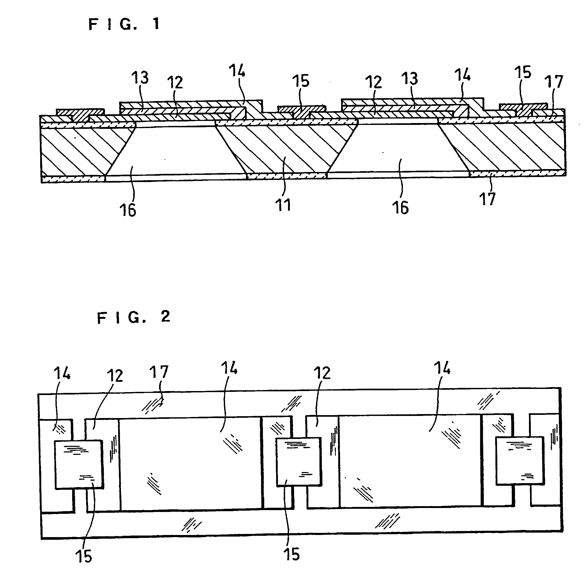
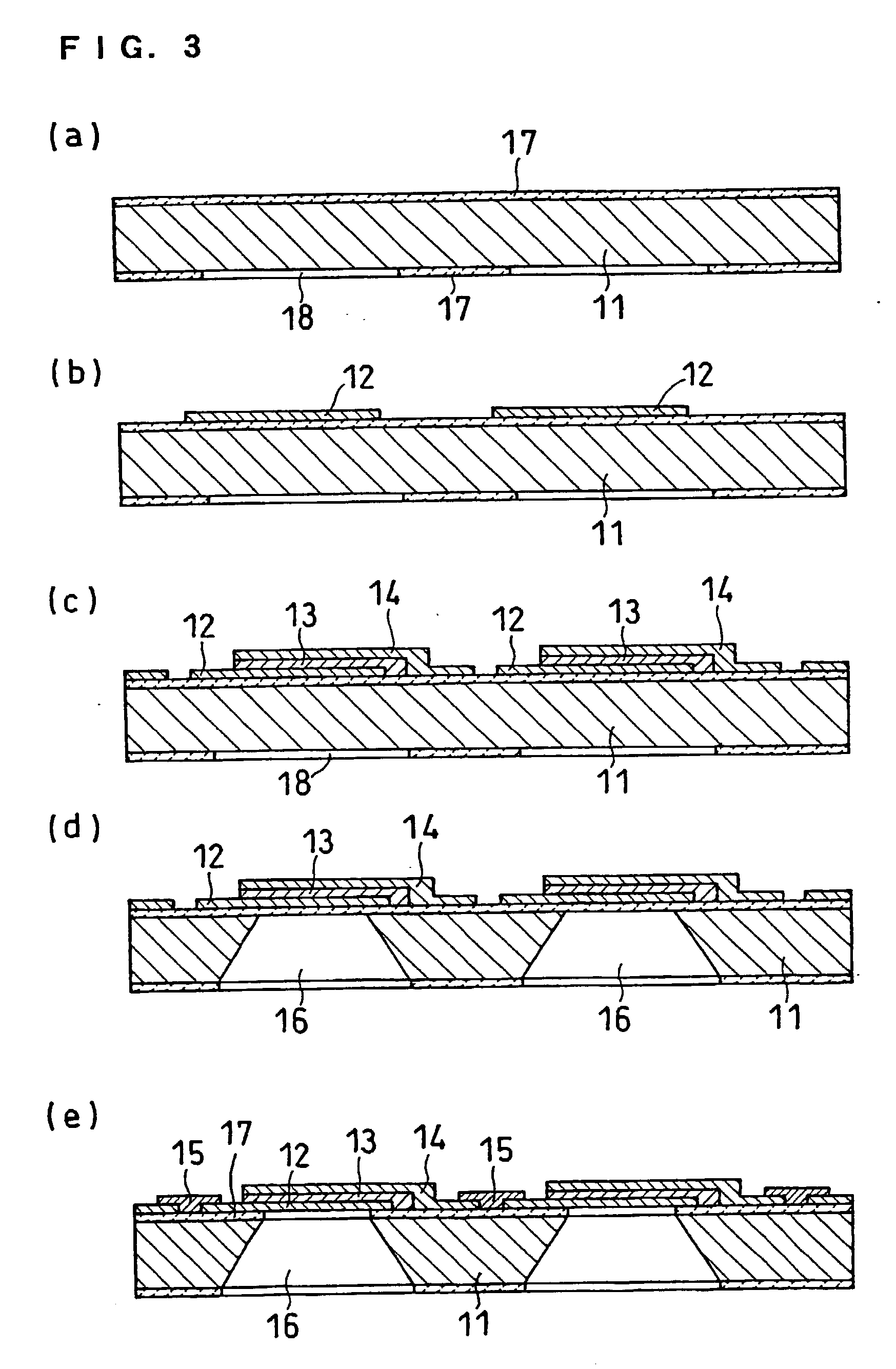
It is difficult to realize a small fuel cell capable of being installed in mobile device by merely downsizing a conventional fuel cell without changing the configuration. The present invention provides a small fuel cell employing a polymer electrolyte thin film, by using a semiconductor process. A polymer electrolyte thin film fuel cell in accordance with the present invention comprises: a substrate having a plurality of openings; an electrolyte membrane-electrode assembly formed on the substrate so as to cover each of the openings, the assembly comprising a first catalyst electrode layer, a hydrogen ion conductive polymer electrolyte membrane and a second catalyst electrode layer which are formed successively; and fuel and oxidant supply means for supplying a fuel or an oxidant gas to the first catalyst electrode layer through the openings, and an oxidant gas or a fuel to the second catalyst electrode layer.

Description

[0001] The present invention relates to polymer electrolyte fuel cells intended for such applications as portable electronic information terminal equipment including cellular phones, computers or the like, small electronic medical equipment, or micro-electromechanical components.[0002] A fuel cell using a polymer electrolyte generates electric power and heat simultaneously by electrochemical reaction of a fuel gas containing hydrogen and an oxidant gas containing oxygen such as air. This fuel cell is basically constructed by a pair of electrodes, namely, an anode and a cathode, formed respectively on both surfaces of a polymer electrolyte membrane that selectively transports hydrogen ions. In general, the above-mentioned electrode comprises a catalyst layer composed mainly of a carbon powder carrying a platinum group metal catalyst, and a diffusion layer which has both gas permeability and electronic conductivity and is formed on the outside surface of this catalyst layer.[0003] In ...

Claims


Application Information

Patent Timeline
IPC IPC(8): H01M4/88H01M4/92H01M8/04H01M8/10H01M8/24
CPCH01M4/8807Y02T90/32H01M4/8871H01M4/8892H01M4/921H01M8/04171H01M8/04223H01M8/04261H01M8/04291H01M8/04552H01M8/0488H01M8/0687H01M8/1011H01M8/1097H01M8/241H01M8/249H01M2250/20Y02E60/523H01M4/881H01M8/04197Y02E60/50Y02T90/40H01M8/2457H01M8/2418H01M8/04225
Inventor FUJII, SATORUHATOH, KAZUHITOHOSAKA, MASATOYUASA, KOHJINOGUCHI, YASUTAKASHIBUTANI, SATOSHITANAKA, AOIHOJO, NOBUHIKOOKADA, YUKIHIRO
Owner PANASONIC CORP
Why Eureka
Try Eureka