Biocompatible bonding method and electronics package suitable for implantation

a biocompatible and electronics technology, applied in the direction of printed element electric connection formation, semiconductor/solid-state device details, therapy, etc., can solve the problems of biocompatible connection, high number of stimulation electrodes cannot be achieved without sacrifice, and each of these materials has limitations on its use as implants

Active Publication Date: 2003-12-18
CORTIGENT INC +1
View PDF7 Cites 194 Cited by
  • Summary
  • Abstract
  • Description
  • Claims
  • Application Information

AI Technical Summary

Problems solved by technology

Packaging of a biomedical device intended for implantation in the eye, and more specifically for physical contact with the retina, presents a unique interconnection challenge.
It is possible to fabricate a suitable electrode array using discrete wires, but with this approach, a high number of stimulation electrodes cannot be achieved without sacrificing cable flexibility (to a maximum of about 16 electrodes).
However, none of these methods results in a biocompatible connection.
Each of these materials has limitations on its use as an implant.
Indium corrodes when placed in a saline environment.
Gold, although relatively inert and biocompatible, migrates in a saline solution, when electric current is passed through it, resulting in unreliable connections.
However, encapsulation proves difficult to effectively implement with this method.
Because the gap between the chip and the flex circuit is not uniform, under fill with epoxy is not practical.
Thus, electrical insulation cannot be achieved with conventional under fill technology.
Further, as briefly discussed earlier, gold, while biocompatible, is not completely stable under the...

Method used


Image

  • Biocompatible bonding method and electronics package suitable for implantation
  • Biocompatible bonding method and electronics package suitable for implantation
  • Biocompatible bonding method and electronics package suitable for implantation

Examples


Embodiment Construction

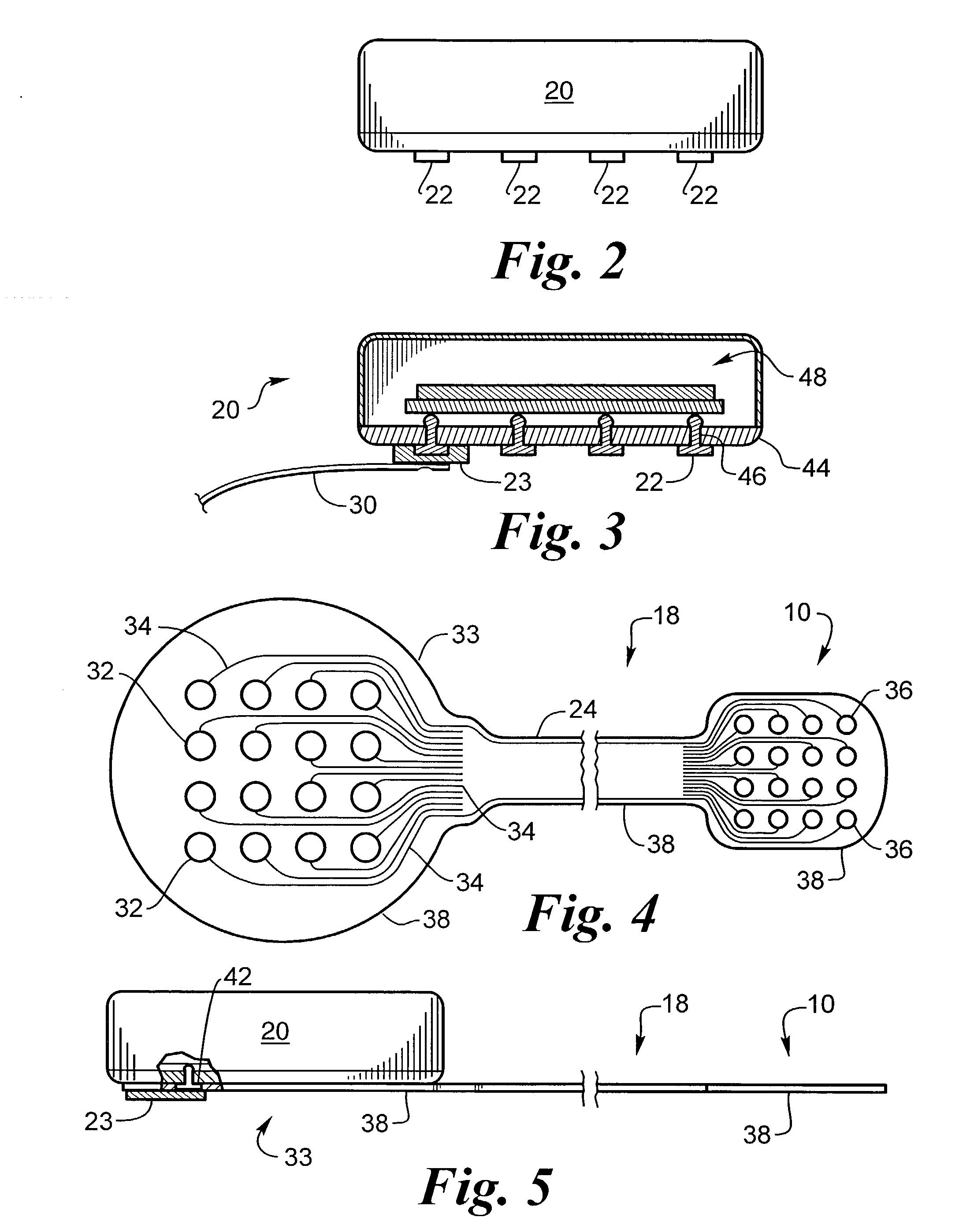
[0110] A flexible electrically insulating substrate comprised of a first substrate 37 and a second substrate 38 of polyimide having a total thickness of 6 um. It had 700 first substrate holes 57, an equal number of matching bond pad holes 64, and an equal number of matching second substrate holes 59, all in alignment so as to create a continuous hole through flexible assembly 66 that terminates on routing 35, arranged in 100 groups of seven on about 40 um centers, FIG. 4a. The hybrid substrate 44 was alumina and the routing 35 was platinum. The bond pad 63 was platinum.

[0111] The assembly was cleaned by rinsing three times in 10% HCl. It was further prepared by bubbling for 10 seconds at + / -5V at 1 Hz in phosphate buffered saline Finally, it was rinsed in deionized water.

[0112] The electroplating set up according to FIGS. 14 and 15 was comprised of an electroplating cell 400 that was a 100 ml beaker with an electroplating solution level 411 at about the 75 ml level. The solution was...


PUM


Abstract

The invention is directed to a method of bonding a hermetically sealed electronics package to an electrode or a flexible circuit and the resulting electronics package, that is suitable for implantation in living tissue, such as for a retinal or cortical electrode array to enable restoration of sight to certain non-sighted individuals. The hermetically sealed electronics package is directly bonded to the flex circuit or electrode by electroplating a biocompatible material, such as platinum or gold, effectively forming a plated rivet-shaped connection, which bonds the flex circuit to the electronics package. The resulting electronic device is biocompatible and is suitable for long-term implantation in living tissue.

Description

[0001] This application is a continuation-in-part of U.S. patent application Ser. No. 10 / 174,349, filed on Jun. 17, 2002, entitled "Biocompatible Bonding Method and Electronics Package Suitable for Implantation."[0002] This application claims the benefit of commonly assigned U.S. patent application, "Platinum Electrode and Method for Manufacturing the Same," Attorney Docket No. S176-USA, filed on Aug. 23, 2002 and incorporated herein by reference.[0004] This invention relates to an electrode array or flexible circuit, electronics package and a method of bonding a flexible circuit or electrode array to an integrated circuit or electronics package.[0005] Arrays of electrodes for neural stimulation are commonly used for a variety of purposes. Some examples include U.S. Pat. No. 3,699,970 to Brindley, which describes an array of cortical electrodes for visual stimulation. Each electrode is attached to a separate inductive coil for signal and power. U.S. Pat. No. 4,573,481 to Bullara des...

Claims


Application Information

Patent Timeline
IPC IPC(8): A61N1/05A61N1/375H05K1/03H05K3/00H05K3/32H05K3/36H05K3/40H05K3/42H05K3/46
CPCA61N1/0543H01L2924/1461A61N1/375A61N1/3758H01L21/563H01L23/4985H01L2924/01046H01L2924/01077H01L2924/01078H01L2924/01079H01L2924/14H05K1/0306H05K3/321H05K3/328H05K3/361H05K3/4015H05K3/423H05K3/4652H05K3/4691H05K2201/09127H05K2201/1028H05K2201/10287H05K2201/10295H05K2201/10977H05K2203/0733H05K2203/1446H01L2224/16225H01L2224/32225H01L2224/73204H01L2924/01019A61N1/36046H01L2924/00H01L2224/0557H01L2224/05571H01L2224/05573H01L2924/00014H01L2224/05599H01L23/49827H01L23/49838H01L24/81H01L2224/13169H01L2224/13178H01L2224/16227H01L2224/81469H01L2224/81478H01L2224/81815H05K1/028H05K1/09H05K1/111H05K1/113H05K1/115H05K1/189H05K3/10H05K3/188H05K3/305H05K3/3436H05K3/4038H05K3/4084H05K3/4644H05K13/0469H05K2203/05H05K2203/06H05K2203/09H05K2203/107
Inventor GREENBERG, ROBERT J.TALBOT, NEILOK, JERRYNEYSMITH, JORDANZHOU, DAO MIN
Owner CORTIGENT INC
Why Eureka
Try Eureka