

Method and device for decontaminating waters which are loaded wiith organic halogen compounds (halogenated hydrocarbons)
a technology of organic halogen compounds and water, applied in the direction of multi-stage water/sewage treatment, other chemical processes, separation processes, etc., can solve the problems of limited adsorption capacity, poor efficiency of corresponding processes, and initial relocation
- Summary
- Abstract
- Description
- Claims
- Application Information
AI Technical Summary
Problems solved by technology
Method used
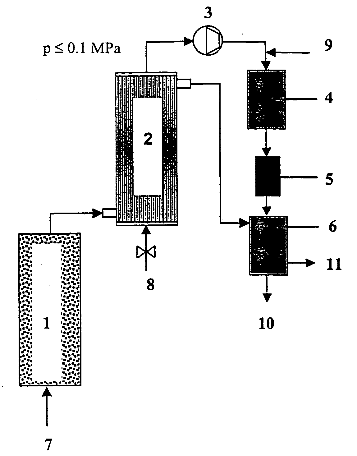
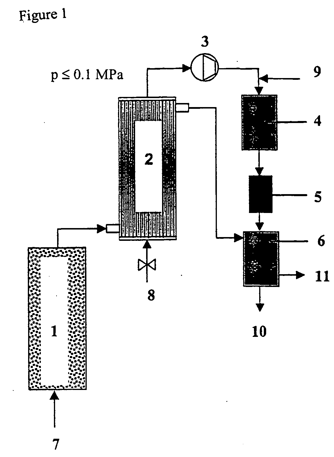
Image

Examples
example 1
Generation of Hydrogen in a Fixed Bed of Iron Granulate
[0065] In column tests, a technically available, macroporous iron batch (3-5 mm particle diameter, 800 m.sup.2 / kg BET surface area) was run with CHC-contaminated groundwater for several weeks (water throughput 1000 pore volumes) until a steady state was reached. The approximately constant rate of hydrogen formation measured in the 4.sup.th week of operation was about 0.5 l / kg.sub.Fe.multidot.d. The column effluent had a pH value of 6.8 to 7.5.
[0066] An assumed contamination of 20 mg / l TeCE requires about 11.4 l of H.sub.2 per m.sup.3 of groundwater for complete hydrodechlorination according to the reaction equation C.sub.2H.sub.2Cl.sub.4+4H.sub.2<C.s-ub.2H.sub.6+4HCl. The bulk density of iron in a fixed-bed reactor is about 3.5 kg / l. A maximum throughput of 156 m.sup.3 of groundwater per m.sup.3 iron-packed reactor volume and day (=6.5 v / vh) follows from these data, if the amount of hydrogen generated by iron corrosion is to cov...
example 2
Dehalogenation in Aqueous Phase
[0070] 1 g of a commercially available Pd catalyst (0.5 wt.-% Pd on .gamma.-Al.sub.2O.sub.3) in pelletized form (d.sub.pellet about 2-3 mm) was added to 1 l of a hydrogen-saturated solution of HHC(CH.sub.2Cl.sub.2, CCl.sub.4, bromoform, VC, TCE, PCE, 1,1,2,2-TeCE, chlorobenzene, 5 mg / l each time) in drinking-water. The solution was agitated at 15.degree. C. overnight. The following compounds were detected by gas-chromatographic analysis: methane, ethene, ethane (none quantified), CH.sub.2Cl.sub.2 (5 mg / l), CHCl.sub.3 (0.5 mg / l), TeCE (4 mg / l), and benzene (3.5 mg / l). The analysis demonstrates that the majority of the HHC had undergone complete dehalogenation. CCl.sub.4 reacts both in one go to form methane and by stepwise dechlorination to form chloroform which in turn undergoes further dechlorination at a much slower rate. Methylene chloride does not react under these conditions, TeCE only very slowly.
[0071] In a second test, the drinking-water was re...
example 3
Dehalogenation in Gaseous Phase
[0072] A stream of gas (50 ml / min) comprised of 95 vol.-% N.sub.2, 4.5 vol.-% H.sub.2 and 0.5 vol.-% O.sub.2 was passed at 15.degree. C. through the drinking-water (.gtoreq.5 l stock) described in Example 2 and spiked with a HHC cocktail. The stream of gas loaded with water vapor and HHC according to their particular vapor pressures was passed over the Pd catalyst used in Example 2 (100 mg, particle diameter <1 mm, tube reactor with 4 mm inner diameter) at a temperature of 250.degree. C. The reactor load was about 30,000 v / vh. The stripping gas was subjected to gas-chromatographic analysis upstream and downstream of the dehalogenation reactor. The main products were methane, ethane, benzene and cyclohexane. In addition, traces of methylene chloride and ethyl chloride were detected. It was possible to operate the reactor for several days without notable loss of activity under these conditions (with secondary metering of stripped HHC into the aqueous pha...
PUM
| Property | Measurement | Unit |
|---|---|---|
| Fraction | aaaaa | aaaaa |
| Fraction | aaaaa | aaaaa |
| Pressure | aaaaa | aaaaa |
Abstract
Description
Claims
Application Information