Photoelectric conversion device

a conversion device and photoelectric technology, applied in light-sensitive devices, electrolytic capacitors, electrochemical generators, etc., can solve the problems of inability to absorb visible light, semiconductors can only absorb ultraviolet portions of sunlight, and the band gap is too large to efficiently absorb sunlight, so as to prevent initial degradation

Inactive Publication Date: 2004-12-02
MATSUSHITA ELECTRIC WORKS LTD +1
View PDF6 Cites 23 Cited by
  • Summary
  • Abstract
  • Description
  • Claims
  • Application Information

AI Technical Summary

Benefits of technology

0063] Hereinafter, the configuration and effect of the photoelectric transducer of the present invention will be specifically illustrated by way of examples, in which initial degradation is pr...

Problems solved by technology

However, when the oxidation force of the oxidation-reduction solution is too large, an oxide film is formed on the surface of the semiconductor, and a light current stops within a short period of time.
However, such a polymer has a problem in durability, and can be used stably for at most several days.
However, this bandgap is too large to efficiently absorb sunlight having a peak intensity in the vicinity of 2.5 eV.
Therefore, such a semiconductor can only absorb an ultraviolet portion of sunlight, and cannot absorb a visible light region occupying the greatest part of sunlight.
As a result, a photoelectric conversion efficiency is very low.
However, unlike natural chlorophyll that is always exchanged for new chlorophyll, a dye used in a solar battery has a problem in stability.
Furthermore, the photoelectric conversion efficiency for the solar battery does not reach 0.5%.
Therefore, it is very difficult to directly imitate the process of photosynthesis in the natural world to constitute a solar battery.
Actually, the conduction mechanism of electrons becomes complicated, which in turn results in a problem of an increased loss of li...

Method used


Image

  • Photoelectric conversion device
  • Photoelectric conversion device
  • Photoelectric conversion device

Examples


example 2

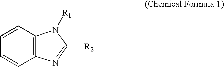
[0068] An electrolytic solution was obtained by dissolving 0.6 mol / dm.sup.3 of dimethylpropylimidazolium iodide, 0.1 mol / dm.sup.3 of iodine, and 0.5 mol / dm.sup.3 of N-methylbenzoimidazole in 3-methoxypropionitrile. A photoelectric transducer was produced in the same way as in Example 1, except that an electrolyte layer having the above composition was used.

example 3

[0069] An electrolytic solution was obtained by dissolving 5.times.10.sup.-5 mol / dm.sup.3 of N-methylbenzoimidazole and 0.5 mol / dm.sup.3 of iodine in a mixed solvent composed of 99% by weight of 1-methyl-3-propylimidazolium iodide and 1% by weight of water. A photoelectric transducer was produced in the same way as in Example 1, except that an electrolyte layer having the above composition was used.

example 4

[0070] An electrolytic solution was obtained by dissolving 0.6 mol / dm.sup.3 of dimethylpropylimidazolium iodide, 5.times.10.sup.-5 mol / dm.sup.3 of N-methylbenzoimidazole, and 0.1 mol / dm.sup.3 of iodine in polyethylene glycol (number-average molecular weight NW: 200). A photoelectric transducer was produced in the same way as in Example 1, except that an electrolyte layer having the above composition was used.


PUM


Abstract

A photoelectric transducer 1 includes a semiconductor electrode 15 provided with a semiconductor layer 7 supporting a sensitizing dye, a counter electrode 9 opposed to the semiconductor electrode 15, and an electrolyte layer 13 disposed between the semiconductor electrode 15 and the counter electrode 9, wherein the electrolyte layer 13 includes a compound containing a nitrogen atom having non-shared electron pairs in a molecule and iodine (I3<->) with a concentration of 0.06 to 6 mol/dm<3>, whereby a photoelectric transducer capable of maintaining an excellent conversion efficiency for a long period of time can be provided.

Description

[0001] The present invention relates to a photoelectric transducer. More specifically, the present invention relates to a photoelectric transducer capable of maintaining an excellent conversion efficiency for a long period of time.[0002] Solar batteries are anticipated as remarkably clean energy sources, and pn-junction type solar batteries have already been put to practical use. On the other hand, photochemical batteries that obtain electric energy by using a chemical reaction in a photoexcitation state have been developed by a number of researchers. As far as practical use is concerned, the photochemical batteries fall behind the pn-junction type solar batteries that have achieved satisfactory results.[0003] Among conventional photochemical batteries, dye-sensitized wet solar batteries, composed of a sensitizer and an electron receptor, using an oxidation-reduction reaction are known. For example, there is a battery composed of a combination of a thionine dye and an iron (II) ion....

Claims


Application Information

Patent Timeline
IPC IPC(8): H01G9/20H01M14/00
CPCH01G9/2009H01G9/2013H01G9/2031H01G9/2059H01M14/005Y02E10/542
Inventor SEKIGUCHI, TAKASHIGRAETZEL, MICHAEL
Owner MATSUSHITA ELECTRIC WORKS LTD
Why Eureka
Try Eureka