Liquid delivery system with horizontally displaced dispensing point

a liquid delivery system and horizontal displacement technology, applied in the direction of liquid handling, container discharging methods, packaged goods types, etc., can solve the problems of affecting the operation, affecting the operation, and affecting the operation, so as to increase the operation speed of the liquid dosing assembly, offset the heat, and the effect of reducing the number of valves

Active Publication Date: 2005-01-20
CHART INC
View PDF6 Cites 25 Cited by
  • Summary
  • Abstract
  • Description
  • Claims
  • Application Information

AI Technical Summary

Benefits of technology

[0020] In the cryogen dosing units employed with the present invention, a pneumatic actuator is used drive the needle valve, the actuator including a solenoid valve to regulate the flow of gas to a piston which in turn controls the opening and closing of the needle valve of the dosing head. In order to increase the operational speed of the liquid dosing assembly, it is possible to thermally manage the unit by positioning the solenoid valve in close proximity to the piston such that it makes thermal contact. The solenoid valve itself is cooled by the expansion of the gas used to drive the piston, as it is exhausted. This cooling effect is used to offset the heat generated by the rapid cycling. By utilizing the cooling effects generated by the solenoid valve in the operation of the needle valve, the needle valve can be operated much more rapidly without resultant overheating.
[0021] In yet another embodiment of this invention, exhausted nitrogen gas is used to further cool the actuator assembly by passing it over the assembly before being exhaust...

Problems solved by technology

However, because of the physical layout and limitations of conveyor systems used to bring containers to a capping or closure station, the size of the liquid delivery system head, and the configuration of the closure station itself, it is presently necessary to inject the liquid nitrogen a distance upstream of the point of closure.
In so doing, the force of injection can cause the droplets to substantially penetrate the surface of the container contents.
The force of impact can result in splash-back of the contents onto the dosing head, where the splashed liquid may accumulate and later interfere with the operation of the dosing head itself.
As a result, heat tends to build up as the pneumatic valve i...

Method used


Image

  • Liquid delivery system with horizontally displaced dispensing point
  • Liquid delivery system with horizontally displaced dispensing point
  • Liquid delivery system with horizontally displaced dispensing point

Examples


Embodiment Construction

[0034] The Horizontal Displacement Assembly

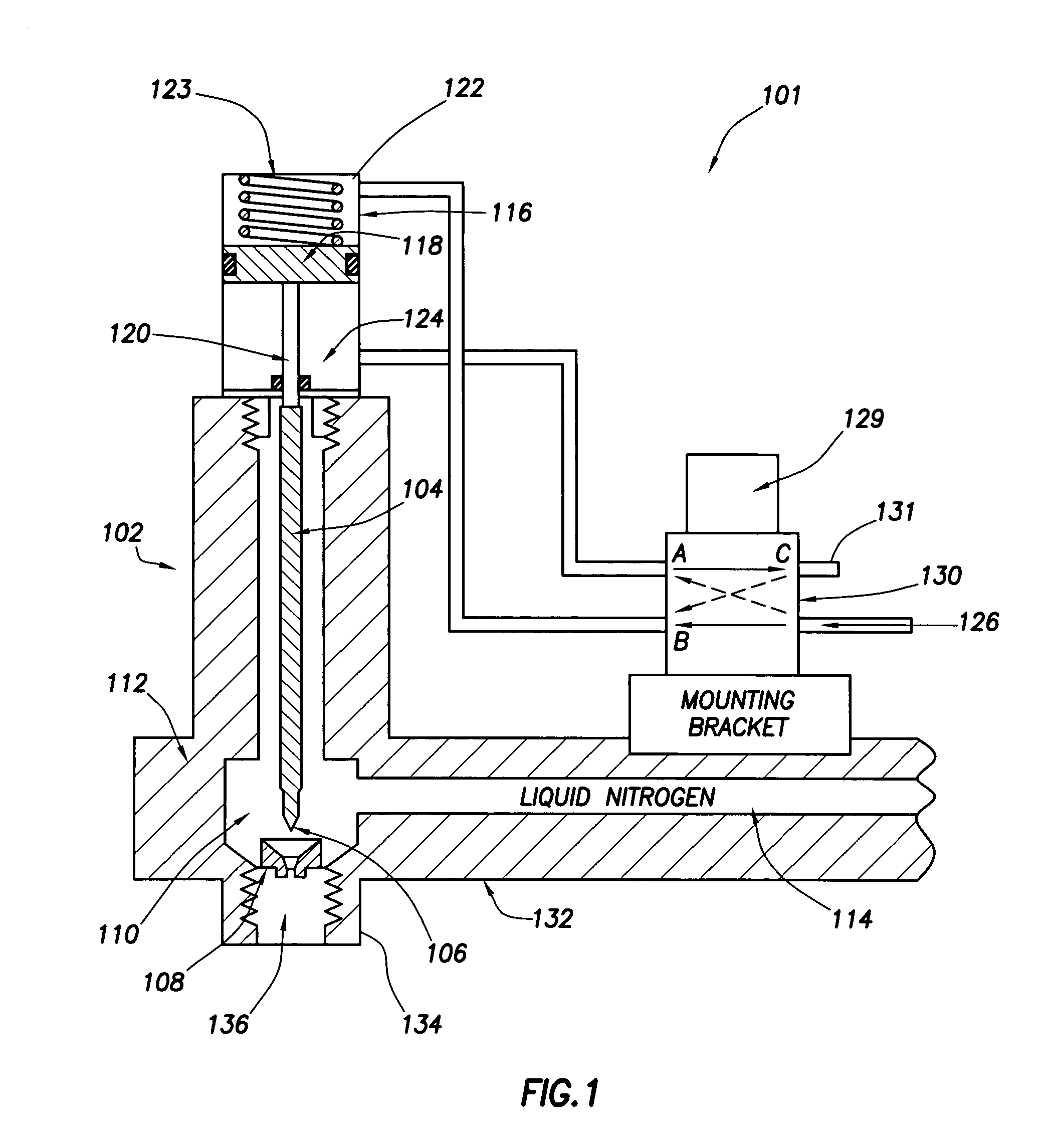
[0035] A typical dose assembly 101 sold by VBS is illustrated in FIG. 1, whereby droplets of liquid nitrogen are metered from a dosing head 102. The dosing head 102 includes a needle valve system for dispensing of the liquid nitrogen, the needle valve including a valve stem 104, with valve head 106 at its distal end, the valve head 106 sized for sealable engagement with valve seat 108. Reservoir 110 defined by valve body 112 acts as a local liquid cryogen supply chamber for holding liquid cryogen, inundating the seating area of the needle valve. Liquid nitrogen is fed to reservoir 110 through source conduit 114, extending from flexible dosing arm 132. It is contained in chamber 110 at slightly elevated pressure, e.g. 1 PSI above atmospheric. In a passive system, the pressure is created by the hydrostatic head of a larger cryogen source reservoir (not shown) placed above and supplying conduit 114. This liquid nitrogen supply may be pressuri...


PUM

PropertyMeasurementUnit
Angleaaaaaaaaaa
Angleaaaaaaaaaa
Temperatureaaaaaaaaaa

Abstract

A method and apparatus is provided for the efficient and controllable delivery of cryogen liquid droplets into thin walled containers before they are sealed, the pressurization of the sealed container caused by the evaporation of the liquid cryogen causing the walls of the container to stiffen. Discharge of the droplets immediately upstream of the container sealing station is facilitated using a horizontal displacement assembly to transport metered droplets from a liquid dosing unit to the point of injection above the container. The horizontal displacement assembly may be provided with internal heaters to prevent freeze up, and a sensor to confirm droplet discharge. It may also be provided with a separate source of heated nitrogen gas, which can be used to back purge the dispensing unit should it become clogged, to melt any frozen liquid occlusions which may have formed in the cryogen supply line. In one embodiment, the solenoid used to actuate the piston regulating the opening and closing of the needle valve, which meters the dispensing of droplets, is mounted in thermal contact with said piston, this placement of the solenoid serving to cool the piston and thus prevent overheating in the case of rapid cycling.

Description

CROSS-REFERENCE TO RELATED APPLICATIONS [0001] This application claims benefit of U.S. provisional patent application Ser. No. 60 / 487,022, filed Jul. 14, 2003; U.S. provisional patent application Ser. No. 60 / 510,907, filed Oct. 14, 2004; and U.S. provisional patent application Ser. No. 60 / 538,565, filed Jan. 23, 2004, all of which are herein incorporated by reference.BACKGROUND OF THE INVENTION [0002] 1. Field of the Invention [0003] The present invention relates generally to cryogenic liquid delivery systems and more particularly to managed dosing systems for injecting metered droplets of liquid nitrogen into beverage, food or other product containers as they move along high-speed production lines before being sealed. [0004] 2. Description of the Related Art [0005] With thin walled containers, especially thin walled metal cans and plastic bottles, it has been found useful to stiffen them after filling, but prior to further processing, such as before labeling, shipping and handling ...

Claims


Application Information

Patent Timeline
IPC IPC(8): B65B31/00B67C3/22
CPCB67C3/222B65B31/006
Inventor ZIEGLER, ALAN T.
Owner CHART INC
Why Eureka
Try Eureka