Phototool coating

a technology of phototools and coatings, applied in the field of contact printing, can solve the problems of affecting the throughput of the lithographic process, reducing the yield of products, and affecting so as to prolong the service life of phototools, and reduce the cost of production

Inactive Publication Date: 2005-02-24
3M INNOVATIVE PROPERTIES CO
View PDF22 Cites 27 Cited by
  • Summary
  • Abstract
  • Description
  • Claims
  • Application Information

AI Technical Summary

Benefits of technology

An advantage of at least one embodiment of the present invention is to provide a phototool having a durable coating with low surface energy.
Another advantage of at least one embodiment of the present invention is to extend phototool service life by reducing cleaning requirements.
Another advantage of at least one embodiment of the present invention is to improve circuit making yield, especially in fine pitch circuit making.

Problems solved by technology

A repeating defect caused by small particles that adhere to a phototool during the imaging step of the flexible circuit making process may significantly reduce the product yield.
However, defects in the pattern or the phototool are routinely experienced, especially when the phototool is used repeatedly to print several substrates consecutively without cleaning the phototool.
This greatly affects the throughput of the lithographic process as well as introducing added cost if the defects cannot be eliminated and the phototools must be replaced.
Both glass and chrome are high surface energy materials, which can cause particles of the photoresist or dust to adhere to the phototool.
This can result in inadequate exposure of a given area, which in turn creates defects.
Furthermore, particles that adhere to the phototool can create a gap between the phototool and the photoresist surface, reducing resolution of the resulting image.

Method used


Image

  • Phototool coating
  • Phototool coating
  • Phototool coating

Examples


example 1

Perfluoropolyether silane, prepared as described in U. S. Pat. No. 6,277,485, Example 2 and column 13, lines 44-58, and poly(hexafluoropropyleneoxide-co-difluoromethylene oxide) alcohol ethoxylated phosphate(“perfluoropolyether phosphate”), available from Aldrich as Catalog # 45,767-1, were diluted into a hydrofluoroether solvent available under the trade name NOVEC Engineered Fluid HFE-7100 from 3M Company (St. Paul, Minn.). The concentrations were approximately 0.075 wt % ECC-1000 and 0.025 wt % perfluoropolyether phosphate.

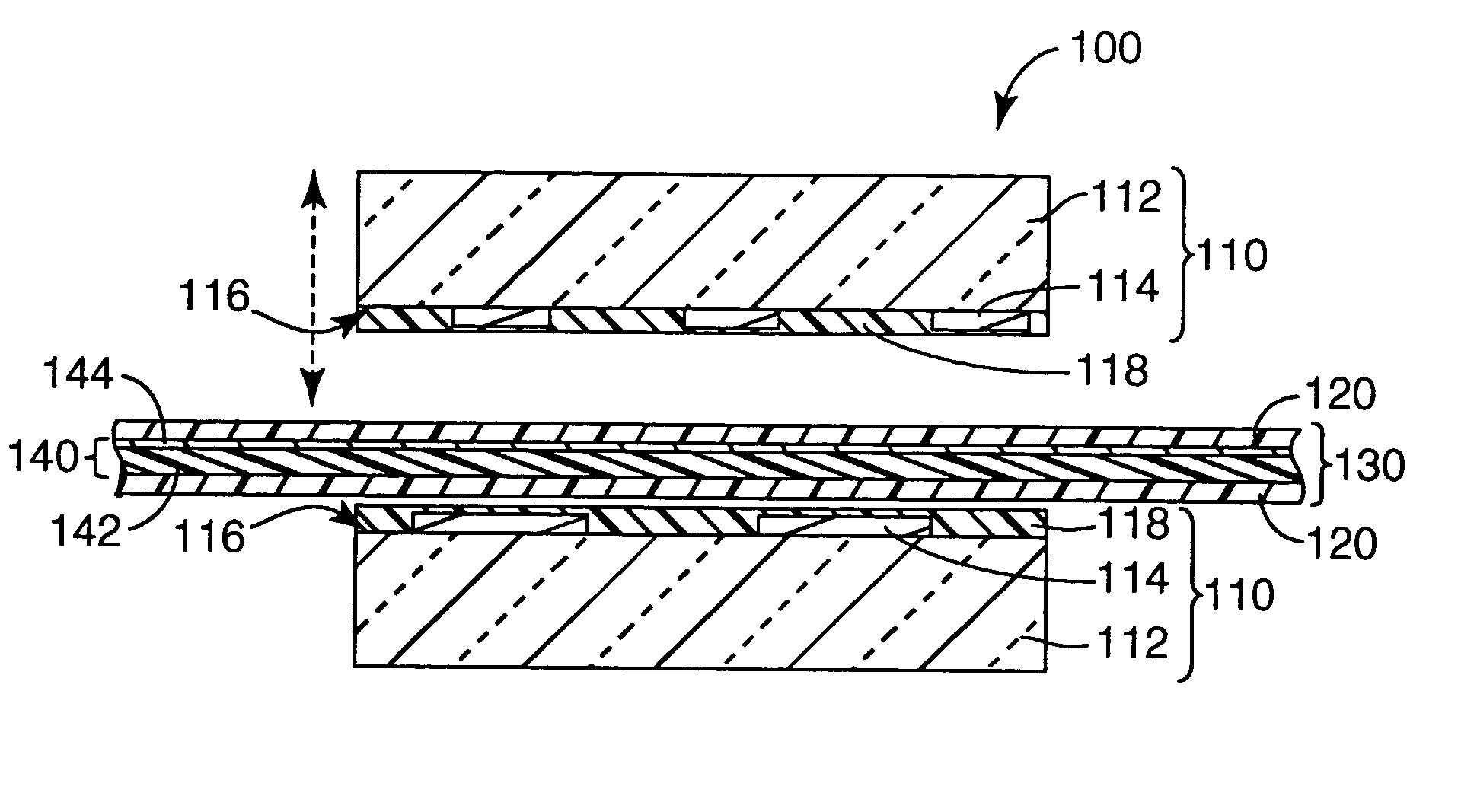
A phototool comprising a glass substrate, pattern-coated with chromium oxide was cleaned by sonication in isopropyl alcohol, then 10 min exposure to air plasma using a Harrick (Ossining, N.Y.) PDC-3×G plasma cleaner / sterilizer. The phototool was then dip coated in the dilute solution. The dip coating withdrawal speed was 3.4 mm / sec using an automated dip coating apparatus. The phototool coating was cured at 120° C. for 30 min. (The dilute solution may, alter...

example 2

The procedure disclosed in J. Fluorine Chem. 1999, 95, 51 was followed for the preparation of the phosphate compound of Formula III. Pyrophosphoric acid (25.5 g, 0.14 mole, Aldrich) was placed in a 250 ml round bottom flask equipped with an overhead stirrer, water condenser, and thermocouple. The acid was heated to 60° C. at which point it was a viscous liquid. To this liquid was added in several two ml portions, C3F7O[CF(CF3)CF2O]nCF(CF3)CONHC2H4OH, (MN=1220, 50 g, 0.041 mole, n=3-10). This addition was slightly exothermic. After the addition was completed, the reaction mixture was held at 60° C. for two hours. Isopropyl acetate (35 ml) was added and the resulting solution then stirred with 150 ml of 2% aqueous HCl for four hours. The lower fluorochemical-containing phase was then separated and dissolved in about 300 ml methyl t-butyl ether (MTBE) and the ether solution then washed twice with an equal volume of 2N HCl solution. The MTBE solution was separated, dried over magnesium...

example 3

To make the compound of Formula I, diethyl (4-aminobenzyl)phosphonate (10 g, 0.041 mole, Aldrich), triethylamine (4.15 g, 0.041 mole) and methyl t-butyl ether (100 ml) were combined in a 250 ml round bottom flask equipped with an overhead stirrer and water condenser under nitrogen. To this mixture was added, dropwise over about 1.5 hours, C3F7O[CF(CF3)CF2O]nCF(CF3)COF, (MW=1017, 41.8 g, 0.041 mole). Near the end of the addition the solution became nearly homogeneous. After stirring for 16 hours at ambient temperature, the solution was diluted with additional MTBE and washed with about 5% aqeuous sodium bicarbonate and then once with 2N HCl. After drying over magnesium sulfate the solvent was removed by rotary evaporation. The amide carbonyl was seen at 1721.5 cm−1 in the infrared spectrum of the resulting product.

Without further purification, the phosphonate was dissolved in diethyl ether and bromotrimethylsilane (17.6 g, 0.115 mole, Aldrich) was added all at once. The solution w...


PUM


Abstract

A phototool having a fluorinated phosph(on)ate coating and methods of using the phototool.

Description

FIELD The present invention relates in general to contact printing and, more particularly, to a coating composition and a method of coating a phototool used in a photolithographic process. BACKGROUND Current product trends in electronics are requiring flexible circuits of finer and finer pitch. A repeating defect caused by small particles that adhere to a phototool during the imaging step of the flexible circuit making process may significantly reduce the product yield. The fabrication of flexible circuits involves the creation of several layers of dielectric and conductive materials that are in intimate contact with layers adjacent to them. At least one of these layers may be patterned by selectively introducing material into or removing material from that layer. The pattern may be created by photolithographic processes. For example, a layer of photoresist material is applied onto the surface of the layer to be patterned. A phototool having transparent and opaque areas in the fo...

Claims


Application Information

Patent Timeline
IPC IPC(8): G03F1/14G03F7/00G03F7/20
CPCB82Y30/00G03F7/2014G03F1/48G03F1/78G03F7/00G03F7/20
Inventor LU, DAVID D.PELLERITE, MARK J.FLYNN, RICHARD M.
Owner 3M INNOVATIVE PROPERTIES CO
Why Eureka
Try Eureka