
Solid oxide fuel cell (SOFC) for coproducing syngas and electricity by the internal reforming of carbon dioxide by hydrocarbons and electrochemical membrane reactor system

a technology of hydrocarbons and carbon dioxide, which is applied in the direction of fuel cells, solid electrolyte fuel cells, cell components, etc., can solve the problems of high energy consumption, endothermic and therefore high energy consumption, and emission of additional greenhouse gases, so as to maximize the effect of co2 utilization

Inactive Publication Date: 2005-04-28
KOREA INST OF SCI & TECH
View PDF7 Cites 38 Cited by
  • Summary
  • Abstract
  • Description
  • Claims
  • Application Information

AI Technical Summary

Benefits of technology

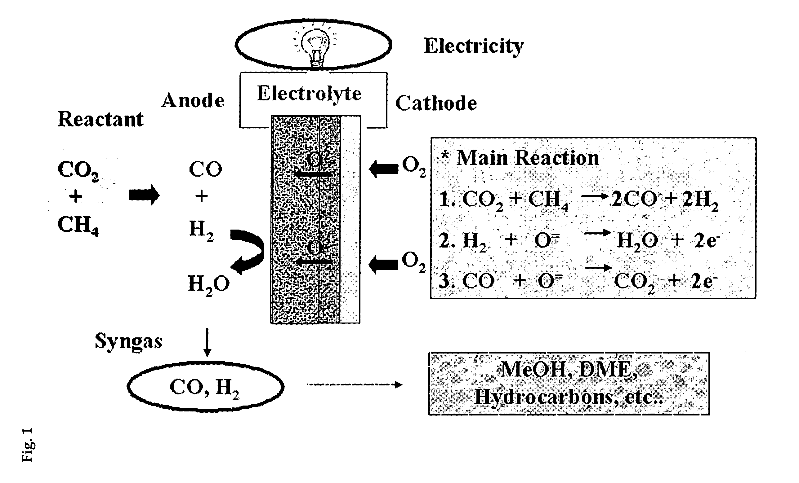
[0014] The present invention has developed a highly efficient electrochemical conversion system using a novel solid oxide fuel cell permitting to improve significantly the efficiency of energy utilization compared to conventional reforming reactions of CO2 by CH4 and to prevent catalyst deactivation due to carbon deposition through performing internal reforming reaction inside catalyst electrode of a solid oxide fuel cell.
[0016] It is another object of this invention to provide an electrochemical conversion system that is capable of maximizing the effect of CO2 utilization by converting chemically hydrocarbon and carbon dioxide to coproduce a useful syngas and electricity with the help of the solid oxide fuel cell described above.

Problems solved by technology

However, the catalytic reforming reaction of carbon dioxide (CO2) and methane (CH4) is associated with high-energy consumption due to its endothermic reaction as described in Scheme 1 and is very likely to result in catalyst deactivation due to the occurrence of carbon deposition.
Moreover, this reaction is endothermic and therefore requires high energy.
Such disadvantage unavoidably leads to emission of additional greenhouse gases due to energy consumption during the operation of a reforming reaction.

Method used


Image

  • Solid oxide fuel cell (SOFC) for coproducing syngas and electricity by the internal reforming of carbon dioxide by hydrocarbons and electrochemical membrane reactor system
  • Solid oxide fuel cell (SOFC) for coproducing syngas and electricity by the internal reforming of carbon dioxide by hydrocarbons and electrochemical membrane reactor system
  • Solid oxide fuel cell (SOFC) for coproducing syngas and electricity by the internal reforming of carbon dioxide by hydrocarbons and electrochemical membrane reactor system

Examples


example 1

Preparation of Perovskite Type Catalyst

[0038] For manufacturing a perovskite type catalyst having a composition of La1-ySryNi1-xCrxO3 (x=0-1 and y=0-1), metal nitrate was used as a precursor. Oxide having a composition of LaNiO3 [La1-ySryNi1-xCrxO3 (x=0 and y=0)] was prepared by dissolving 8.6604 g of lanthanum nitrate and 5.8162 g of nickel nitrate in 100 g of ultra-pure water. Malic acid was added to the resultant at an extent that the mole ratio of malic acid to total metal ion was 1.5. To the mixed aqueous solution, aqueous ammonia and nitric acid were added dropwise with agitation to adjust pH of the solution to 2.5. The precipitated catalyst precursor was dried at 80□ for 6-12 hr in oven to remove water. The following viscous solution was additionally heated at 100□ for drying. Then, the catalyst precursor was additionally heat-treated at 210□ to thermally decompose NO2 and other gases. The resulting oxide was grinded using a mortar to prepare solid powder and then, heated un...

example 2

Preparation of Ni-YSZ Type Catalyst

[0040] For preparing Ni-YSZ type catalysts [Ni: YSZ: CeO2 (or MgO)=(40-55 wt %): (40-55 wt %): (0-10 wt %)], NiO powder (99.99 Sigma-Aldrich Co.), YSZ powder (8 mol % Y2O3 doped ZrO2, TOSOH Co.), MgO powder (98%, Nakarai Chemical Co.) and CeO2 powder (99.9%, Sigma-Aldrich Co.) were used as a precursor.

[0041] Firstly, Ni, YSZ and CeO2 (or MgO) powder were mixed in a certain amount and subject to attrition milling for 24 hr by use of zirconia ball, obtaining material for catalyst electrode. In addition, Ni-YSZ type catalysts were prepared according to co-precipitation method. Ni-YSZ type catalysts having various compositions were prepared according to the procedures described above. The compositions are summarized in Table 2.

TABLE 2Ni—YSZ—CeO2NiOYSZCeO2Ni—YSZ catalystwt %Ni—YSZ5545—Ni—YSZ—CeO2(2 wt %)54442Ni—YSZ—CeO2(4 wt %)53434Ni—YSZ—MgO(2 wt %)54442Ni—YSZ—MgO(4 wt %)53434

example 3

Manufacture of Electrochemical Cell for SOFC

[0042] The electrochemical single cells of electrolyte or anode supported SOFC were manufactured as follows:

(1) Manufacture of Single Cell for Electrolyte Supported SOFC

[0043] Firstly, YSZ electolyte were processed using molder to prepared pellet with compact structure and sintered at 1400□ for 2 hr, obtaining disk-shaped electrolytes. The thickness and diameter of YSZ electrolyte prepared were 1.2 mm and 22.5 mm, respectively.

[0044] Slurry for coating electrode material was prepared in accordance with the following procedures. 0.87 g of methyl cellulose, 1.14 g of CMC (carbonylmethyl cellulose) and 1.74 g of polyethylene oxide as a binder were added to 0.2 g of electrode material prepared above. 3 ml of isopropyl alcohol as a dispersant was added dropwise to the aqueous solution mixed with binders and agitated to mix well materials in slurry. After 2-hr agitation, slurry for catalyst electrode was prepared.

[0045] In addition, slurry...


PUM


Abstract

The present invention relates to a solid oxide fuel cell for internal reforming of hydrocarbons and carbon dioxide, in particular, to a solid oxide fuel cell in which one side of solid oxide electrolyte (YSZ) is attached to an air electrode (La0.8Sr0.2MnO3) and its other side is attached to a catalyst electrode of Ni-YSZ type or perovskite type metal oxide. The electrochemical conversion system using the solid oxide fuel cell permits the occurrence of internal reforming of hydrocarbons and carbon dioxide concomitantly with the coproduction of a syngas and electricity, and overcomes the shortcomings associated with the catalytic deactivation due to carbon deposition and the high-energy consumption.

Description

BACKGROUND OF THE INVENTION [0001] 1. Field of the Invention [0002] The present invention relates to a solid oxide fuel cell for internal reforming of hydrocarbons and carbon dioxide, in particular, to a solid oxide fuel cell in which one side of solid oxide electrolyte (YSZ) is attached to an air electrode (La0.8Sr0.2MnO3) while its other side is attached to a catalyst electrode of Ni-YSZ type or perovskite type metal oxide. The electrochemical conversion system using the solid oxide fuel cell permits the occurrence of internal reforming of hydrocarbon and carbon dioxide concomitantly with the coproduction of a syngas and electricity, and overcomes the shortcomings associated with the catalyst deactivation due to carbon deposition and the high-energy consumption. [0003] 2. Description of the Related Art [0004] Reforming reactions of carbon dioxide (CO2) and methane (CH4) have been extensively studied as the importance of removal and emission control of greenhouse gases have been hi...

Claims


Application Information

Patent Timeline
IPC IPC(8): H01M4/86H01M4/88H01M4/90H01M4/96H01M8/10H01M8/12
CPCH01M4/8621H01M4/8885H01M4/90Y02E60/50H01M4/9066Y02E60/522H01M4/9033
Inventor MOON, DONG JURYU, JONG WOOPARK, JONG MINLEE, BYUNG GWONLEE, SANG DEUK
Owner KOREA INST OF SCI & TECH
Learn More