
Aneurysm treatment devices and methods

a technology for aneurysms and treatment devices, applied in medical science, surgery, diagnostics, etc., can solve problems such as tissue damage, asymptomatic aneurysms, and formation of blood clots, and achieve the effect of reducing or eliminating the risk of implant migration

Inactive Publication Date: 2006-06-01
BIOMERIX CORP
View PDF78 Cites 133 Cited by
  • Summary
  • Abstract
  • Description
  • Claims
  • Application Information

AI Technical Summary

Benefits of technology

[0019] It is a further object of the invention to provide a method and device for occluding cerebral aneurysms by bio-integrating and sealing off the aneurysm to prevent migration, recanalization, leaking, or reforming.
[0029] The packing density is targeted to achieve angiographic occlusion after embolization of the aneurysm by the implant, followed by clotting, thrombosis, and tissue ingrowth, ultimately leading to biological obliteration of the aneurysm sac. Permanent tissue ingrowth will prevent any possible recanalization.
[0030] It is furthermore preferable that the implant be treated or formed of a material that will encourage such fibroblast immigration. It is also desirable that the implant be configured, with regard to its three-dimensional shape, and its size, resiliency and other physical characteristics, and be suitably chemically or biochemically constituted to foster eventual tissue ingrowth and formation of scar tissue that will help fill and / or obliterate the aneurysm sac.
[0041] Once an aneurysm has been identified using suitable imaging technology, such as a magnetic resonance image (MRI), computerized tomography scan (CT Scan), x-ray imaging with contrast material or ultrasound, and is to be treated, the surgeon chooses which implant he or she feels would best suit the aneurysm, both in shape and size. The implant can be used alone. In another embodiment, the aneurysm treatment device of the invention may also be used in conjunction with a frame of platinum coils to assist in reducing or eliminating the risk of implant migration out of the neck of the aneurysm. This is particularly true in the case of wide neck or giant aneurysms. The chosen implant is then loaded into an intravascular catheter in a compressed state. If desired, the implant can be provided in a sterile package in a pre-compressed configuration, ready for loading into a catheter. Alternatively, the implants can be made available in an expanded state, also, preferably, in a sterile package, and the surgeon at the site of implantation can use a suitable secondary device or a loader apparatus to compress an implant so that it can be loaded into a delivery catheter.

Problems solved by technology

The pressure of an aneurysm against surrounding tissues, especially the pulsations, may cause pain and may also cause tissue damage.
However, aneurysms are often asymptomatic.
The blood in the vicinity of the aneurysm can become turbulent, leading to formation of blood clots, that may be carried to various body organs where they may cause damage in varying degrees, including cerebrovascular incidents, myocardial infarctions and pulmonary embolisms.
Should an aneurysm tear and begin to leak blood, the condition can become life threatening, sometimes being quickly fatal, in a matter of minutes.
However, researchers have identified a gene associated with a weakness in the connective tissue of blood vessels that can lead to an aneurysm.
Cerebral aneurysms frequently occur in otherwise healthy and relatively youthful people and have been associated with many untimely deaths.
Greene's hydrogel lacks the mechanical properties to enable it to regain its size and shape in vivo were it to be compressed for catheter, endoscope, or syringe delivery, and the process can be complex and difficult to implement.
While platinum coils may be having some benefits in this respect, they are inherently expensive, and the pulsation of blood around the aneurysm may cause difficulties such as migration of the coils, incomplete sealing of the aneurysm, or fragmentation of blood clots.
It is also well known that the use of a coil is frequently associated with recanalization of the site, leading to full or partial reversal of the occlusion.
If the implant does not fully occlude the aneurysm and effectively seal against the aneurysm wall, pulsating blood may seep around the implant and the distended blood vessel wall causing the aneurysm to reform around the implant.
The delivery mechanics of many of the known aneurysm treatment methods can be difficult, challenging, and time consuming.
Most contemporary vascular occlusion devices, such as coils, thrombin, glue, hydrogels, etc., have serious limitations or drawbacks, including, but not limited to, early or late recanalization, incorrect placement or positioning, migration, and lack of tissue ingrowth and biological integration.
Also, some of the devices are physiologically unacceptable and engender unacceptable foreign body reactions or rejection.

Method used


Image

  • Aneurysm treatment devices and methods
  • Aneurysm treatment devices and methods
  • Aneurysm treatment devices and methods

Examples


example 1

Fabrication of a Crosslinked Reticulated Polyurethane Matrix

[0137] The aromatic isocyanate RUBINATE 9258 (from Huntsman) was used as the isocyanate component. RUBINATE 9258, which is a liquid at 25° C., contains 4,4′-MDI and 2,4′-MDI and has an isocyanate functionality of about 2.33. A diol, poly(1,6-hexanecarbonate)diol (POLY-CD CD220 from Arch Chemicals) with a molecular weight of about 2,000 Daltons was used as the polyol component and was a solid at 25° C. Distilled water was used as the blowing agent. The blowing catalyst used was the tertiary amine triethylenediamine (33% in dipropylene glycol; DABCO 33LV from Air Products). A silicone-based surfactant was

TABLE 1Ingredient used (TEGOSTAB ® BF 2370from Goldschmidt). A cell-opener wasused (ORTEGOL ® 501 fromGoldschmidt). The viscosity modifierpropylene carbonate (from Sigma-Aldrich)was present to reduce the viscosity. Theproportions of the components that wereused are set forth in the following table:Parts by WeightPolyol Com...

example 2

Reticulation of a Crosslinked Polyurethane Foam

[0146] Reticulation of the foam described in Example 1 was carried out by the following procedure: A block of foam measuring approximately 15.25 cm×15.25 cm×7.6 cm (6 in.×6 in.×3 in.) was placed into a pressure chamber, the doors of the chamber were closed, and an airtight seal to the surrounding atmosphere was maintained. The pressure within the chamber was reduced to below about 100 millitorr by evacuation for at least about two minutes to remove substantially all of the air in the foam. A mixture of hydrogen and oxygen gas, present at a ratio sufficient to support combustion, was charged into the chamber over a period of at least about three minutes. The gas in the chamber was then ignited by a spark plug. The ignition exploded the gas mixture within the foam. The explosion was believed to have at least partially removed many of the cell walls between adjoining pores, thereby forming a reticulated elastomeric matrix structure.

[0147...

example 3

Histological Evaluation of a Plurality of Crosslinked Reticulated Polyurethane Matrix Implants in a Canine Carotid Bifurcation Aneurysm Model

[0154] An established animal model of cerebral aneurysms was used to evaluate the histologic outcomes of implanting a plurality of cylindrical implants machined from a block of cross-linked reticulated polyurethane matrix as described in Example 2. The three animals were sacrificed at the three-month timepoint to assess tissue response to the cross-linked reticulated polyurethane matrix.

[0155] One of two different implant configurations was used in this experiment. The first configuration was a cylindrical implant measuring 6 mm diameter×15 mm length. The second configuration was a segmented, cylindrical implant measuring 3 mm diameter×15 mm length. To machine the implants, a rotating die cutter was used to cut 3 mm and 6 mm diameter cylinders. The implants were then trimmed to 15 mm in length. Implant dimensions were tested for acceptability...


PUM


Abstract

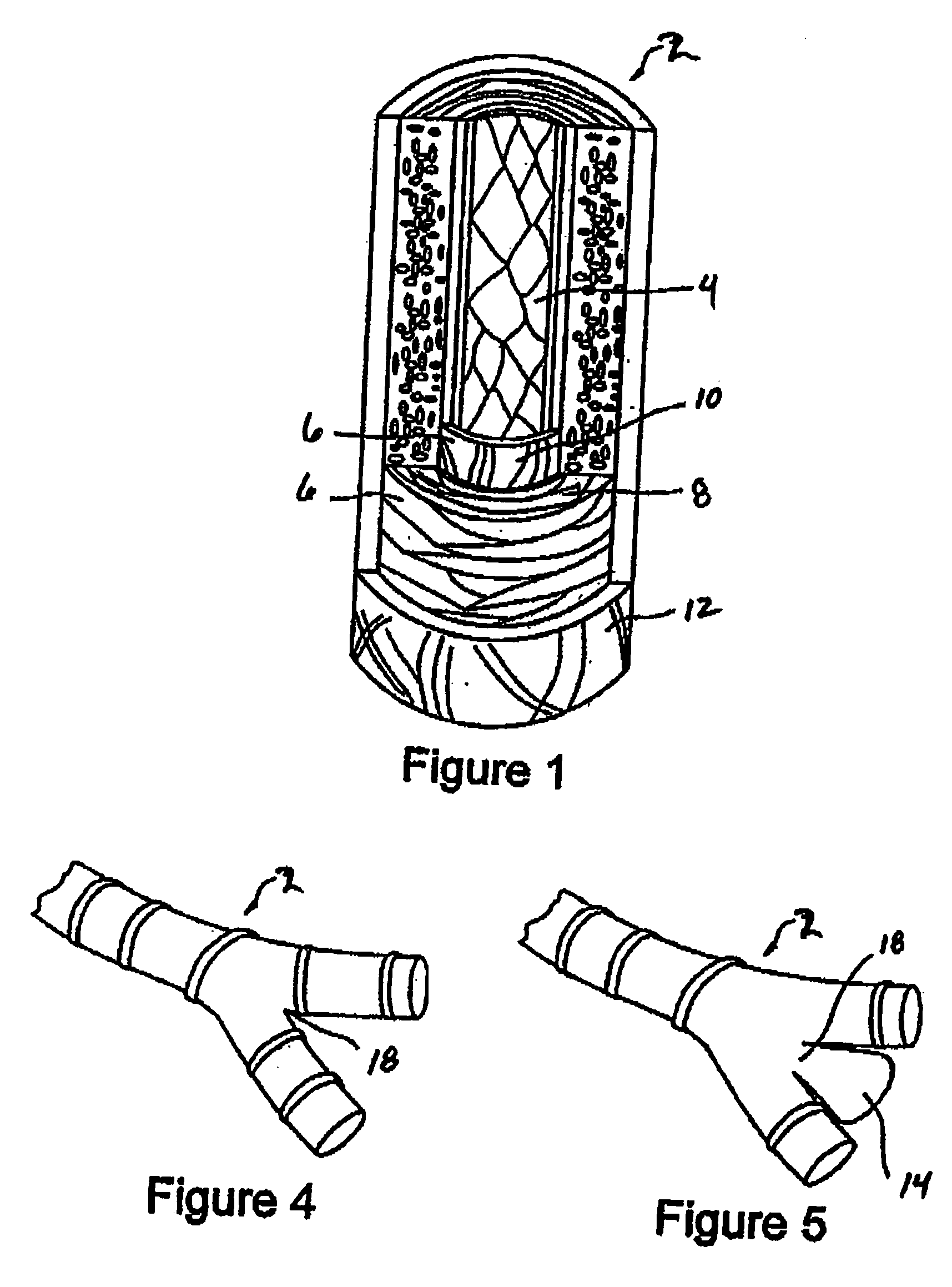
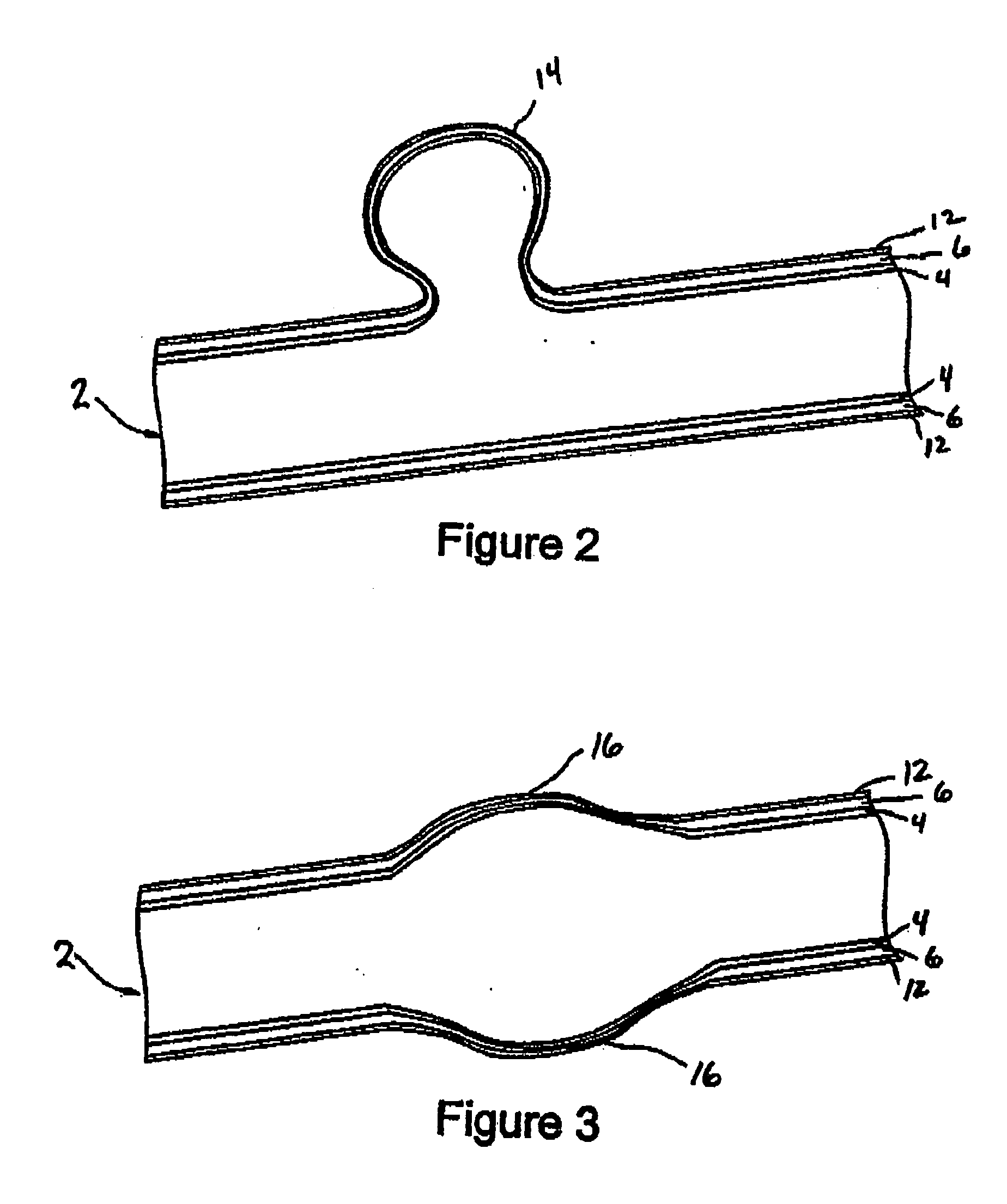
An aneurysm treatment device for in situ treatment of aneurysms comprises a collapsible member having a first shape wherein the first shape is an expanded geometric configuration, and a second shape, wherein the second shape is a collapsed configuration that is loadable into a catheter. The aneurysm treatment device is capable or returning to the first shape in the sac of an aneurysm upon deployment, where it occludes the aneurysm. In another embodiment an occlusion device comprises a flexible, longitudinally extending elastomeric matrix member that assumes a non-linear shape to conformally fill a targeted vascular site.

Description

CROSS-REFERENCE TO RELATED APPLICATION [0001] This application is a continuation-in-part of co-pending, commonly assigned U.S. patent application Ser. No. 10 / 998,357, filed Nov. 26, 2004, which is incorporated herein by reference.FIELD OF THE INVENTION [0002] This invention relates to methods and devices for the treatment of vascular aneurysms and other comparable vascular abnormalities. More particularly, this invention relates to occlusion devices for vascular aneurysms that comprise a reticulated elastomeric matrix structure and a delivery device. BACKGROUND OF THE INVENTION [0003] The cardio-vascular system, when functioning properly, supplies nutrients to all parts of the body and carries waste products away from these parts for elimination. It is essentially a closed-system comprising the heart, a pump that supplies pressure to move blood through the blood vessels, blood vessels that lead away from the heart, called arteries, and blood vessels that return blood toward the hear...

Claims


Application Information

Patent Timeline
Patent Type & Authority Applications(United States)
IPC IPC(8): A61M29/00
CPCA61B17/12022A61B17/12113A61B17/12145A61B17/1215A61B17/12163A61B17/12172A61B17/12181A61B19/54A61B2017/00862A61B2017/00867A61B2017/1205A61B2017/12054A61B2017/12095A61B90/39
Inventor SEPETKA, IVANABOYTES, MARIAJORDAN, MAYBELLEFRIEDMAN, CRAIGDATTA, ARINDAM
Owner BIOMERIX CORP
Learn More