High performance magnetic composite for ac applications and a process for manufacturing the same

a composite material and high-performance technology, applied in the field of soft or temporary magnetic composites for ac applications, can solve the problems of energy loss, hysteresis loss and eddy current loss, conversion of electric energy to thermal energy, etc., and achieve the effect of improving magnetic properties and lowering hysteresis and eddy current losses

Inactive Publication Date: 2006-06-15
CORP IMFINE INC
View PDF9 Cites 21 Cited by
  • Summary
  • Abstract
  • Description
  • Claims
  • Application Information

AI Technical Summary

Benefits of technology

[0022] An object of the present invention is to provide a magnetic composite for AC applic

Problems solved by technology

The energy losses, or core losses, as they are sometimes called, result in conversion of electric energy to thermal energy.
These are hysteresis losses and eddy current losses.
These currents which travel normal to the direction of the magnetic flux lead to an energy loss through Joule (resistance) heating.
This material loss could be very costly with some specific alloys.
Also, mass production of laminations prevents design with rounded edges to help copper wire winding.
Due to the planar nature of the laminations, their use limits the design of devices with 2 dimensions distribution of the magnetic field.
Indeed, the field is limited to travel only in the plane of the laminations.
The cost of the laminations is related to their thickness.
This increases the rolling cost of the material and decreases the stacking factor of the final part due to imperfect surface finish of the laminations and burrs and the relative importance of the insulating coating.
Laminations are thus well suited but limited to low frequency applications.
The limitation of the SMC is their high hysteresis losses and low permeability compared to steel laminations.
Additionally, to prevent the destruction of the insulation or coating, SMC can very hardly be fully annealed or achieve a complete recry

Method used


Image

  • High performance magnetic composite for ac applications and a process for manufacturing the same
  • High performance magnetic composite for ac applications and a process for manufacturing the same
  • High performance magnetic composite for ac applications and a process for manufacturing the same

Examples


example 1

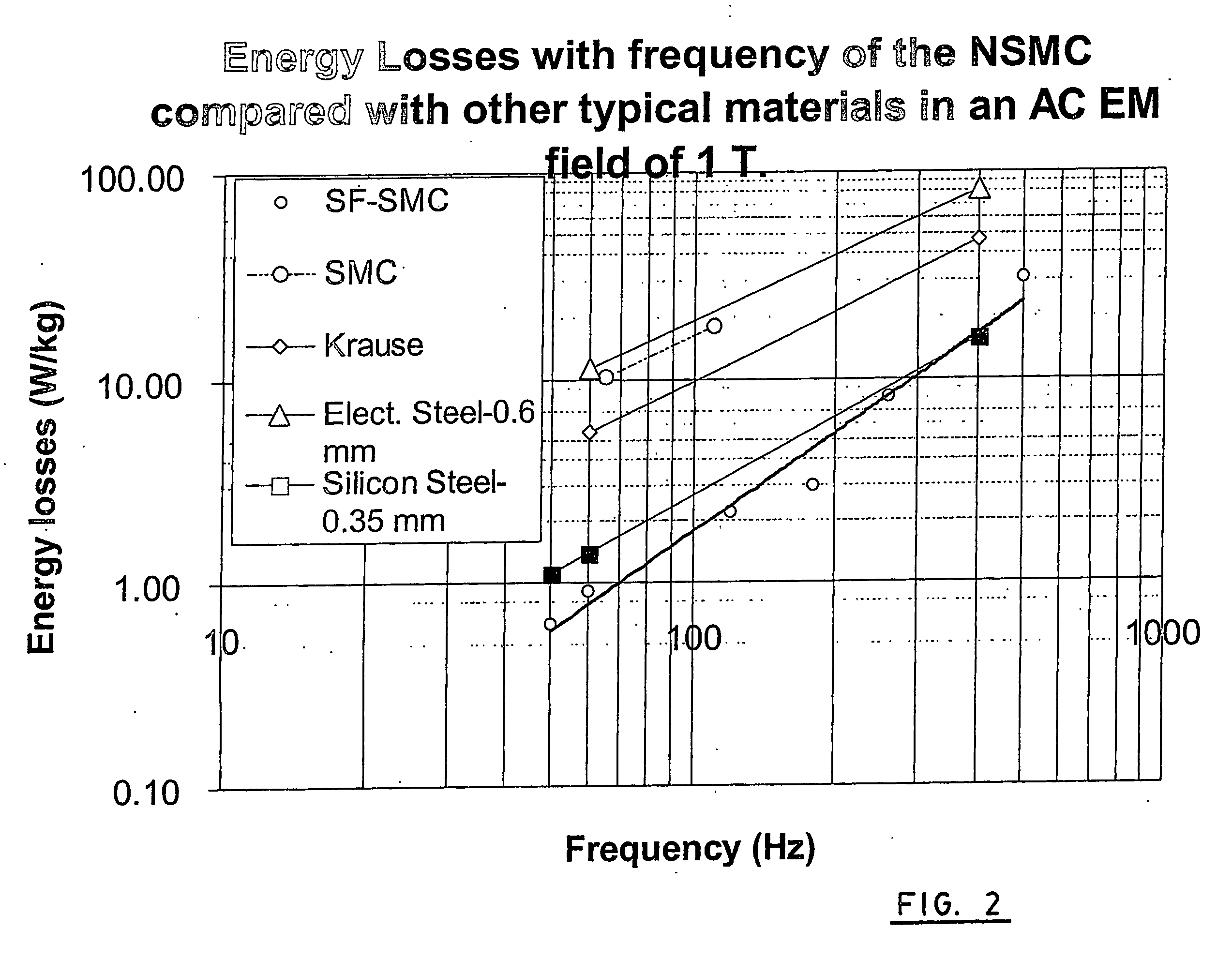
[0076] The process used to do the rings for which results are reported on table 1 (SF-SMC FeNi sintered) and FIG. 2 at an induction of 1.0 Tesla is the following: [0077] Coating one side of a 50 μm thick Fe47.5% Ni foil with 0.4 μm of alumina in D.C. pulsed magnetron sputtering reactive process, [0078] Annealing the ribbon during 4 hours at 1200° C. under pure hydrogen, [0079] Cutting the ribbon to form square lamellar particles of 2 mm by 2 mm sides, [0080] Mixing the particles with 0.5% acrawax in a “V” type mixer during 30 minutes, [0081] Filling a plastic pre-filling die with the mixture, vibrating the pre-filling die during filling, pressing at 1 MPa, [0082] Sliding the content of the pre-filling die into the steel die for cold pressing, pressing at 827 MPa and ejecting the compact, [0083] Delubing the compact at 600° C. during 15 minutes, [0084] Heating the compact at 1200° C. under pure hydrogen during 30 minutes, and [0085] Cooling the compact at 20° C. / min.

[0086] A part of...

example 2

[0087] The process used to do the rings which results are reported in table 1 (SF-SMC FeNi forged) on FIG. 3 at an induction of 1.5 Tesla is the following: [0088] Coating one side of a 50 μm thick Fe47.5% Ni foil with 0.4 μm of alumina in D.C. pulsed magnetron sputtering reactive process, [0089] Annealing the ribbon during 4 hours at 1200° C. under pure hydrogen, [0090] Cutting the ribbon to form square lamellar particles of 2 mm by 2 mm sides, [0091] Mixing the particles with 0.5% acrawax in a V type mixer during 30 minutes, [0092] Filling a pre-filling die with the mixture, vibrating the pre-filling die during filling, pressing at 1 MPa, [0093] Sliding the content of the pre-filling die into the die for cold pressing, pressing at 827 MPa and ejecting the compact, [0094] Heating the compact at 1000° C. in air during 3 minutes and forging it at 620 Mpa, [0095] Annealing the compact at 800° C. during 30 minutes under pure hydrogen.

[0096] A part of the same dimensions made with uncoa...

example 3

[0097] The process used to do the rings which results are reported on Table 1 (SF-SMC Fe-3%Si sintered) is the following: [0098] Ribbons of iron containing 3% of silicon are produced by the technology of Planar Flow Casting (The melt product is directly poured on a high speed rotating wheel). [0099] The 50 μm thick ribbon is coated with a spray of a Sol-Gel solution made with aluminum isopropoxyde and dried by reaching 150° C. in a continuous process. [0100] The coated ribbon is annealed under pure hydrogen at 1200° C. during 2 hours and cooled to room temperature slowly. [0101] The ribbons are sprayed another time with the Sol-Gel process. [0102] The ribbons are then sprayed with EBS using an electrostatic charging system and cut into 2 mm by 2 mm square particles. [0103] Particles are poured in a plastic pre-compacting die and pre-compacted at 150 lb per square inch (1 MPa). [0104] The pre-compacted particles are transferred to a steel die (powder metallurgy compacting press) and ...


PUM

PropertyMeasurementUnit
Temperatureaaaaaaaaaa
Thicknessaaaaaaaaaa

Abstract

A magnetic composite for AC applications with improved magnetic properties (i.e. low hysteresis losses and low eddy current losses) is disclosed. The composite comprises a consolidation of magnetizable metallic microlamellar particles each having a top and bottom surfaces and opposite ends. The top and bottom surfaces are coated with a dielectric coating for increasing the resistivity of the composite and reducing eddy current losses. The dielectric coating is made of a refractory material and the ends of the lamellar particles are metallurgically bonded to each other to reduce hysteresis losses of the composite. A process for manufacturing the same is also disclosed. The composite is suitable for manufacturing devices for AC applications such as transformers, stator and rotor of motors, generators, alternators, field concentrators, chokes, relays, electromechanical actuators, synchroresolvers, etc . . . .

Description

FIELD OF THE INVENTION [0001] The present invention relates generally to the field of magnetic materials, more specifically to soft or temporary magnetic composites for AC applications and to the production of the same. More particularly, it concerns a soft magnetic composite with reduced hysteresis and eddy current losses and very good mechanical properties. The magnetic composite of the invention is well suited for manufacturing power application devices such as stator or rotor of machines or parts of relays operating at frequencies up to 10 000 Hz; or chokes, inductors or transformers for frequencies up to 10 000 Hz. BACKGROUND OF THE INVENTION [0002] Magnetic materials can be divided into two major classes: permanent magnetic materials (also referred to as hard magnetic materials) and temporary magnetic materials (also referred to as soft magnetic materials). [0003] The permanent magnets are characterized by a large remanence, so that after removal of a magnetizing force, a high...

Claims


Application Information

Patent Timeline
IPC IPC(8): H01B1/12H01F1/147H01F1/22H01F1/24H01F41/02
CPCH01F1/1475H01F1/22Y10T428/2991H01F41/0246Y10T428/12181H01F1/24
Inventor LEMIEUX, PATRICK
Owner CORP IMFINE INC
Why Eureka
Try Eureka