
Method of forming a dielectric structure having a high dielectric constant and method of manufacturing a semiconductor device having the dielectric structure

a dielectric structure and dielectric structure technology, applied in the direction of machines/engines, mechanical equipment, vacuum evaporation coating, etc., can solve the problems of difficult to secure the high permittivity required, increase the thickness of the gate insulation layer, so as to improve the capacity and electrical characteristics of the semiconductor memory device, improve the dielectric characteristics, and reduce the leakage current through the dielectric structure

Inactive Publication Date: 2006-07-27
SAMSUNG ELECTRONICS CO LTD
View PDF8 Cites 39 Cited by
  • Summary
  • Abstract
  • Description
  • Claims
  • Application Information

AI Technical Summary

Benefits of technology

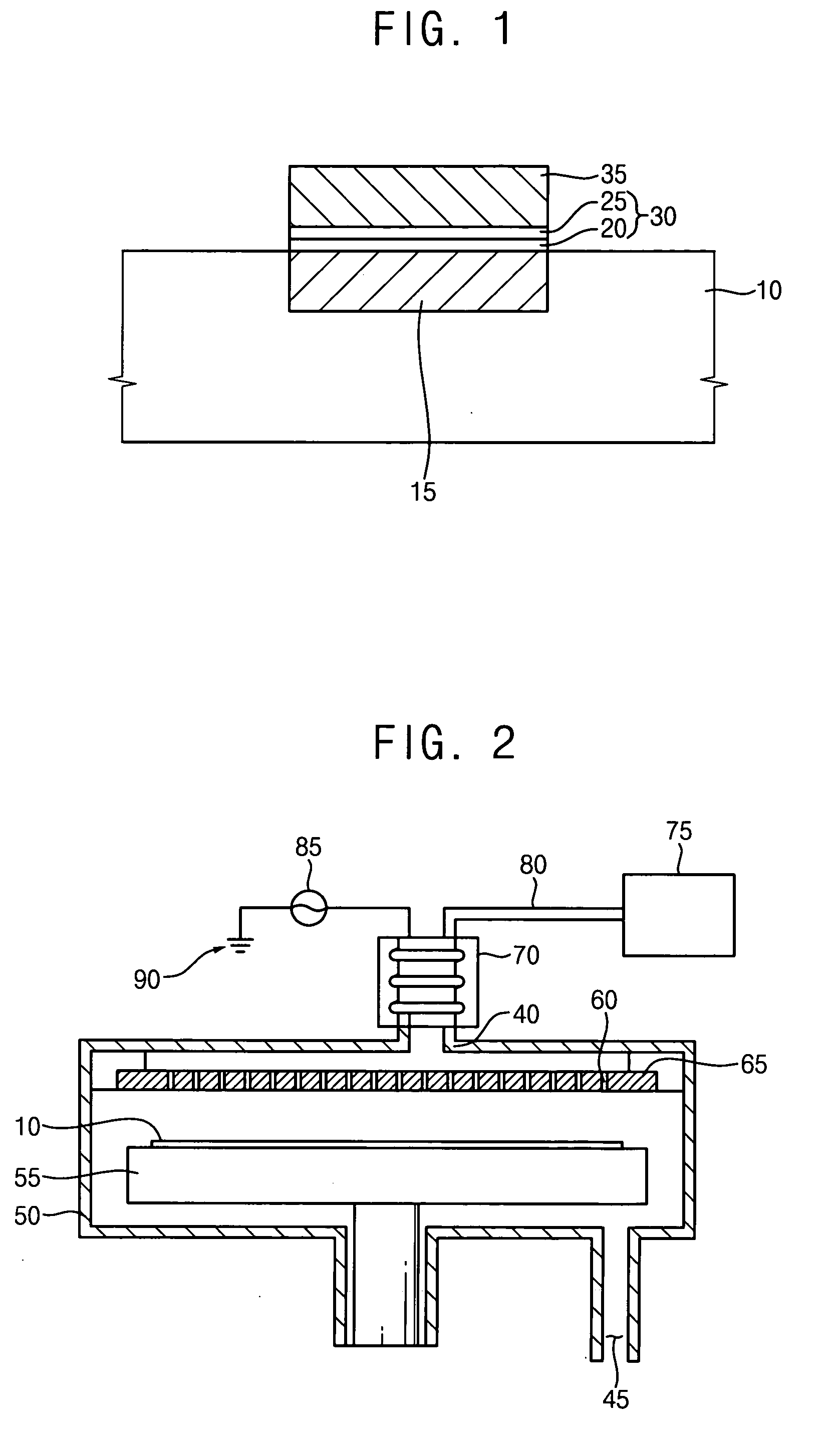
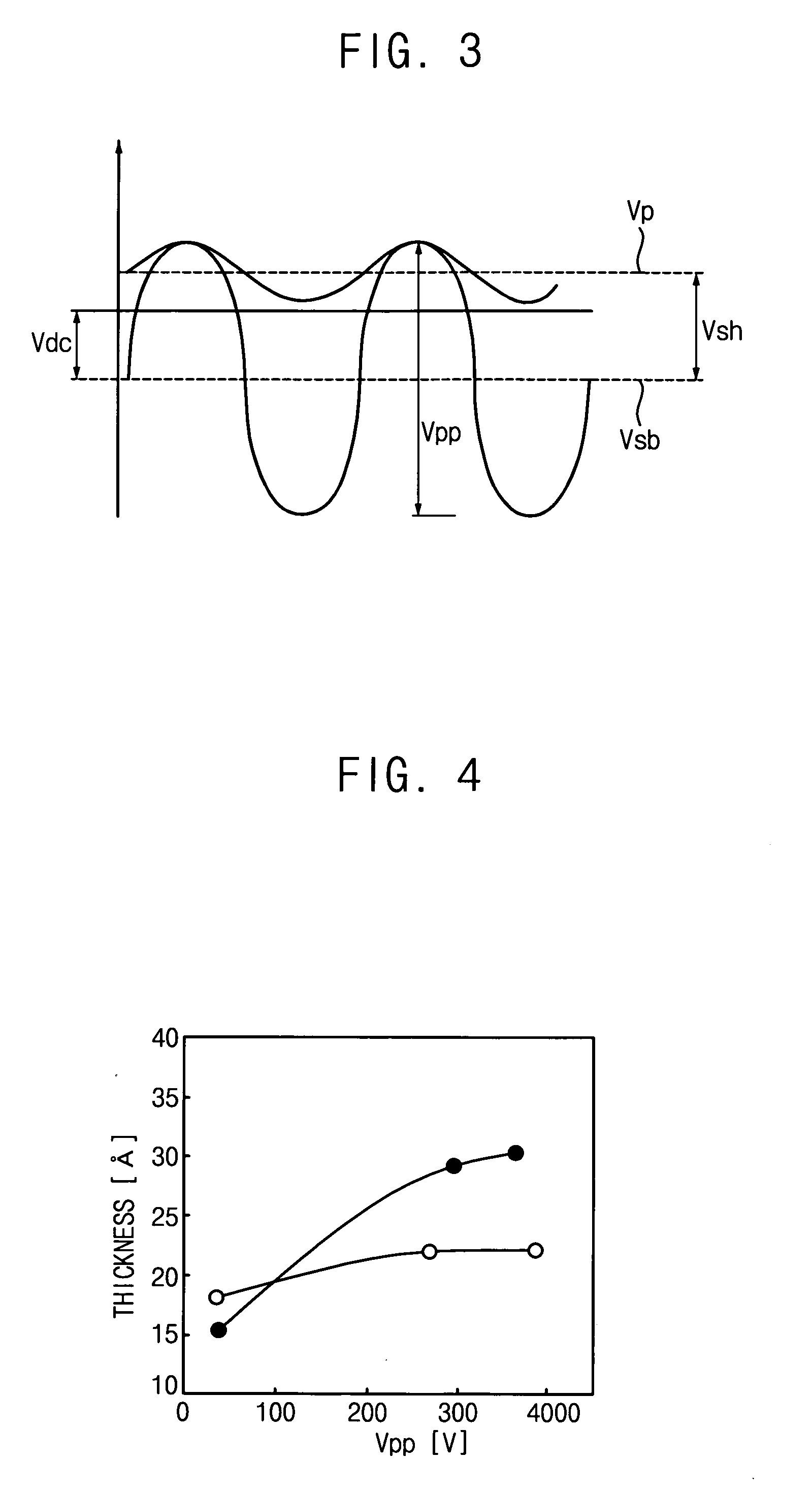
[0035] According to some embodiments of the present invention, a second dielectric layer of a metal oxide doped with silicon having sufficient nitrogen content is formed on a first dielectric layer by treating the first dielectric layer with ammonia plasma or nitrogen plasma while controlling a voltage difference between a ground and a susceptor on which a semiconductor substrate is placed. Therefore, a dielectric structure including the first and the second dielectric layers may have improved dielectric characteristics and a leakage current through the dielectric structure may greatly decrease. Additionally, when the dielectric structure is employed as gate insulation layer and / or a dielectric layer of a volatile semiconductor memory device or a non-volatile semiconductor memory device, capacity and electrical characteristics of the semiconductor memory device may be improved. Since the dielectric structure includes at least one metal silicon oxide layer and at least one metal silicon oxynitride layer, the dielectric structure may have a good heat resistance and a high dielectric constant without being damaged in a heat treatment process. Therefore, the semiconductor memory device may have excellent electrical characteristics.

Problems solved by technology

In this method, even if the hafnium silicon oxide layer can be partially converted into hafnium silicon oxynitride layer, because the hafnium silicon oxide layer is not nitrated enough, it is not easy to secure a high dielectric constant required for the hafnium silicon oxynitride layer.
However, even in this method, because the zirconium oxide layer is not nitrated enough, a thickness of the gate insulation layer increases and it is difficult to secure the high permittivity required.
In a non-volatile semiconductor memory device having this dielectric layer with the ONO construction, because basically a plurality of oxide layers and nitride layers are adopted as a dielectric layer, not only does the dielectric layer not have a permittivity required for the non-volatile semiconductor memory device, but a process of forming the dielectric layer is also complicated.
When the dielectric layer including the metal oxide is adapted to the non-volatile semiconductor memory device, however, the performance of the semiconductor device drops because of a thermal damage in a successive high temperature process.

Method used


Image

  • Method of forming a dielectric structure having a high dielectric constant and method of manufacturing a semiconductor device having the dielectric structure
  • Method of forming a dielectric structure having a high dielectric constant and method of manufacturing a semiconductor device having the dielectric structure
  • Method of forming a dielectric structure having a high dielectric constant and method of manufacturing a semiconductor device having the dielectric structure

Examples


Embodiment Construction

[0046] The present invention is described more fully hereinafter with reference to the accompanying drawings, in which some embodiments of the present invention are shown. The present invention may, however, be embodied in many different forms and should not be construed as limited to the embodiments set forth herein. Rather, these embodiments are provided so that this disclosure will be thorough and complete, and will fully convey the scope of the present invention to those skilled in the art. In the drawings, the sizes and relative sizes of layers and regions may be exaggerated for clarity.

[0047] It will be understood that when an element or layer is referred to as being “on”, “connected to” or “coupled to” another element or layer, it can be directly on, connected or coupled to the other element or layer or intervening elements or layers may be present. In contrast, when an element is referred to as being “directly on,”“directly connected to” or “directly coupled to” another ele...


PUM

PropertyMeasurementUnit
Temperatureaaaaaaaaaa
Fractionaaaaaaaaaa

Abstract

In a method of manufacturing a dielectric structure, after a first dielectric layer is formed on a substrate by using a metal oxide doped with silicon, the substrate is placed on a susceptor of a chamber. By treating the first dielectric layer with a plasma in controlling a voltage difference between the susceptor and a ground, a second dielectric layer is formed on the first dielectric layer. The second dielectric layer including a metal oxynitride doped with silicon having enough content of nitrogen is formed on the first dielectric layer. Therefore, dielectric properties of the dielectric structure comprising the first and the second dielectric layers can be improved and a leakage current can be greatly decreased. By adapting the dielectric structure to a gate insulation layer and / or to a dielectric layer of a capacitor or of a non-volatile semiconductor memory device, capacitances and electrical properties can be improved.

Description

RELATED APPLICATION [0001] This application claims priority under 35 USC § 119 to Korean Patent Application No. 2005-6543 filed on Jan. 25, 2005, the contents of which are herein incorporated by reference in its entirety. FIELD OF THE INVENTION [0002] The present invention relates generally to a method of forming a dielectric structure and a method of manufacturing a semiconductor device including the dielectric structure and, more particularly, to a method of forming a dielectric structure having a high dielectric constant and a method of manufacturing a semiconductor device having same. BACKGROUND OF THE INVENTION [0003] Semiconductor memory devices are generally divided into volatile semiconductor memory devices that lose data over time, such as a dynamic random access memory (DRAM) device and a static random access memory (SRAM) device and nonvolatile semiconductor memory devices that do not lose data over time. Especially, in a volatile semiconductor memory device such as the D...

Claims


Application Information

Patent Timeline
IPC IPC(8): H01L21/471
CPCC23C14/5826C23C14/586C23C16/56H01L21/28273H01L21/3141H01L21/3143H01L21/31645H01L27/10852H01L27/10873H01L27/115H01L27/11521H01L28/40H01L29/513H01L29/517H01L29/78H01L29/40114Y02E10/20Y02E60/16H01L21/02142H01L21/02252H01L21/022H10B12/033H10B12/05H10B69/00H10B41/30H01L21/0228F03B17/062F03B13/06F05B2220/706F05B2220/32
Inventor LEE, JONG-CHEOLKIM, SUNG-TAEKIM, YOUNG-SUNYOO, CHA-YOUNGNAM, GAB-JINPARK, YOUNG-GEUNCHOI, JAE-HYOUNGYEO, JAE-HYUNLIM, HA-JINKIM, YUN-SEOK
Owner SAMSUNG ELECTRONICS CO LTD
Features
  • Generate Ideas
  • Intellectual Property
  • Life Sciences
  • Materials
  • Tech Scout
  • Unparalleled Data Quality
  • Higher Quality Content
  • 60% Fewer Hallucinations
Learn More