
Organic compound and organic electrolumiscent device

a technology of organic compounds and electroluminescent elements, applied in the direction of organic compounds of group 3/13 elements, organic compounds of group 5/15 elements, natural mineral layered products, etc., can solve the problems of insufficient luminescence properties or insufficient element life, inability to efficiently transfer energy, and inability to meet the requirements of luminous efficiency, etc., to achieve the effect of improving luminous efficiency

Inactive Publication Date: 2006-08-31
DAI NIPPON PRINTING CO LTD
View PDF6 Cites 15 Cited by
  • Summary
  • Abstract
  • Description
  • Claims
  • Application Information

AI Technical Summary

Benefits of technology

[0012] The inventor of the present invention found out the following facts, in course of studying the organic EL element suitable for coating in a coating process and exhibiting a high luminous efficiency. That is, there is found that easiness of coating and evenness in dispersion are improved by containing EM molecules and CTM molecules into a compound and binding them with a molecular chain having solubility to a solvent, and there is found that the intermolecular distance and the relative orientation between the host and guest, which are most closely adjacent to each other and which are bonded by the added molecular chain, can be optimized, and the luminous efficiency on recombination can be remarkably improved, in comparison with the conventional coating method. The present invention has been accomplished from these findings.
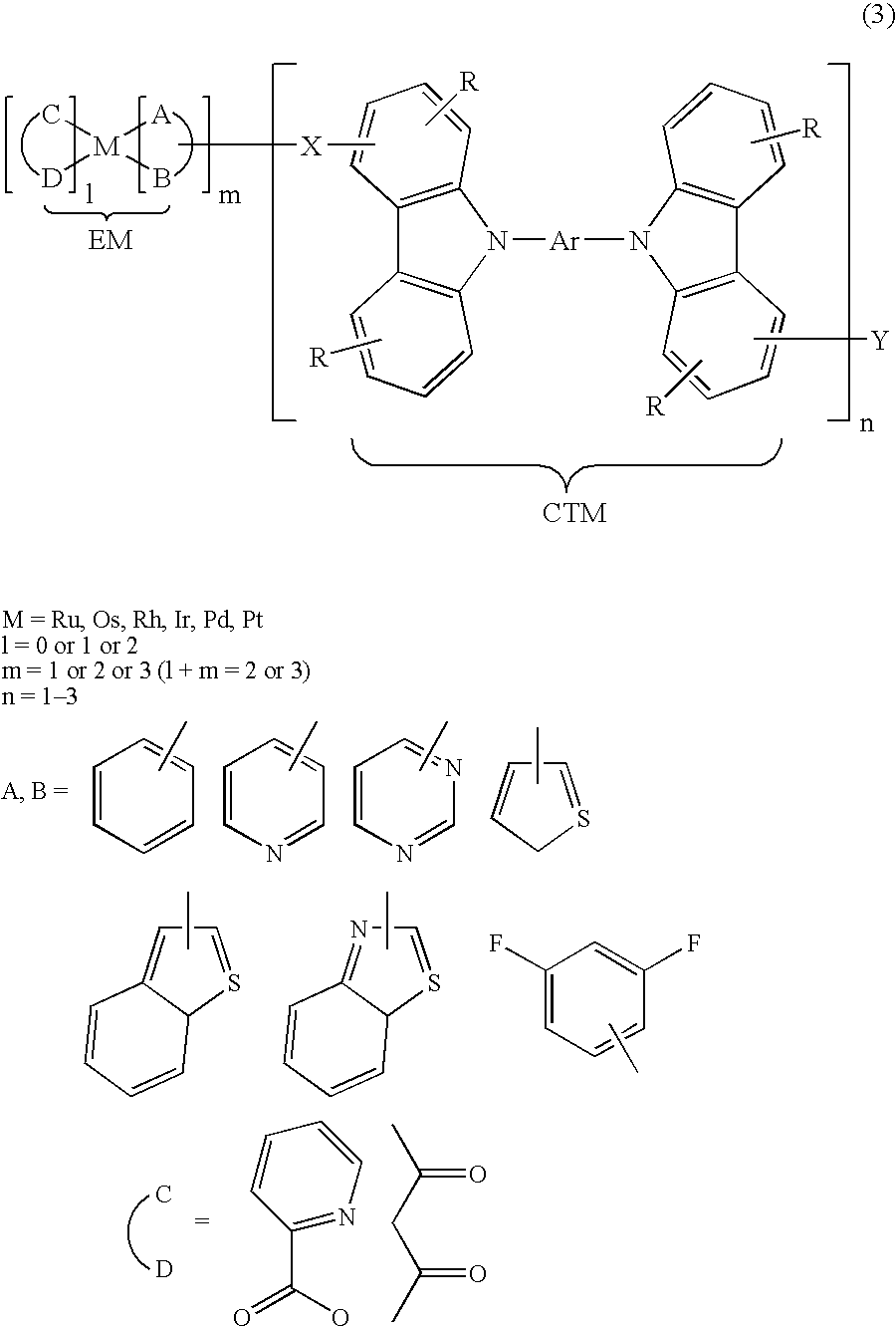
[0016] The organic compounds according to these first to third embodiments are compounds represented by these general formulae (1) to (3), in which each light emitting material EM and each charge transporting material CTM are bonded by each chemical bonding chain X. These compounds tend to dissolve uniformly in the solvent or tend to disperse easily, due to a good solubility of the chemical bonding chain X. Thereby, it is possible to obtain a uniform luminescence property at each part on a material to be coated, because these organic compounds can disperse without agglomerating in the coating film, by applying a coating material containing any of these compounds onto the material to be coated. Furthermore, in these organic compounds of the present invention, their chemical bonding chain X optimizes the relative orientation and intermolecular distance between a host and a guest, which are most closely adjacent, and also acts as a barrier for preventing the charge migration. Thereby, it is possible to ensure the hopping conduction from the charge transporting material CTM to the light emitting material EM, and achieve further improved luminous efficiency when used for an organic EL element. Particularly, in the second and third embodiments, since they include each substituent Y, the solubility of the compounds can be improved, due to the effect of each substituent Y. Since each substituent Y acts so as to give a stereo hindrance to these compounds, this substituent Y can prevent the agglomeration of the compounds when these compounds dissolve or disperse in a solvent, and thereby can disperse these compounds uniformly, almost monodispersely, in a low or high molecular binder composing an organic compound layer. The uniform disperse of the compounds in the film or layer means a uniform light emission in a plane or surface, on the basis of injected charges, and thereby can contribute to the improved luminous efficiency.
[0028] In these organic EL elements of the present invention, at least one layer of the organic compound layers contain any of the organic compounds of the present invention. The organic compounds according to the present invention, in which each light emitting material EM and each charge transporting material CTM are bonded by each chemical bonding chain X, tend to soluble uniformly in the solvent or tend to disperse easily, due to a good solubility of the chemical bonding chain X. Thereby, it is possible to obtain a uniform luminescence property at each part on a material to be coated, because these organic compounds can disperse without agglomerating in the coating film, by applying a coating material containing any of these compounds onto the material to be coated. Furthermore, in the case that the chemical bonding chain X includes a saturated hydrocarbon chain, a direct and spatial energy migration can be achieved between the charge transporting material CTM and the light emitting material EM, without passing any bridge (cross-linking) group. Therefore, it can present not only higher luminous efficiency, but also the light emission due to the EM. Particularly, in the second and third embodiments, since they include each substituent Y, the solubility of the compounds can be improved, due to the effect of each substituent Y. Since each substituent Y acts so as to give a stereo hindrance to these compounds, this substituent Y can prevent the agglomeration of the compounds when these compounds dissolve or disperse in a solvent, and thereby can disperse these compounds uniformly, almost monodispersely, in a low or high molecular binder composing an organic compound layer. The uniform disperse of the compounds in the film or layer means a uniform light emission in a plane or surface, on the basis of injected charges, and thereby can contribute to the improved luminous efficiency.
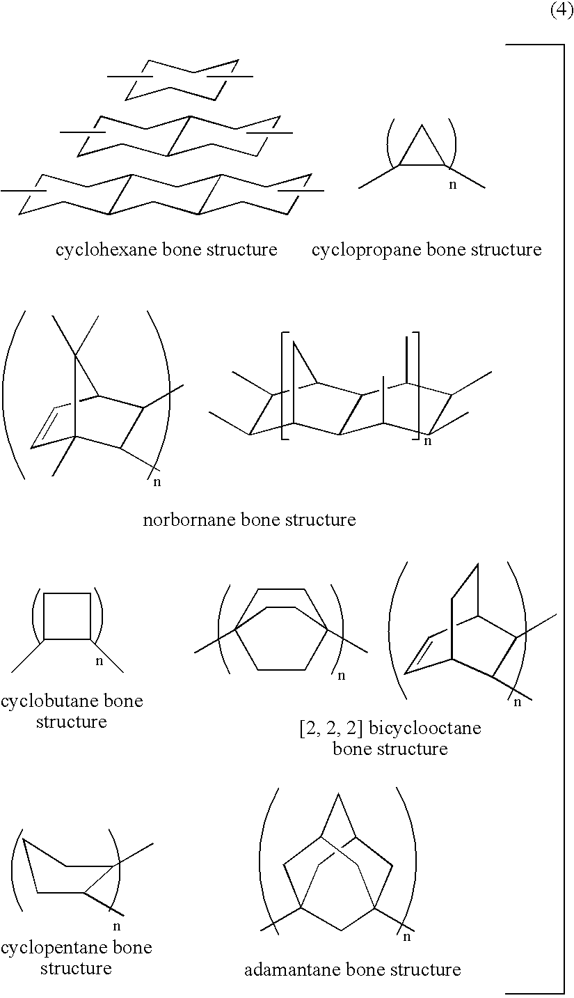
[0030] According to this invention, since the intermolecular distance between the light emitting material EM and the charge transporting material CTM is controlled to a predetermined length for ensuring the solubility of the compounds and / or the hopping conduction, the effect on these organic compound layers can be stable. In this case, in order to improve the solubility to a solvent, the chemical bonding chain X needs to be elongated, which may deteriorate the charge transporting property (charge migration property) between molecules. However, by adding each substituent Y for supplementing the solubility to a solvent, it is possible to achieve a chemical structure exhibiting a good charge transporting property. The length thereof is preferably controlled to 0.1 to 20 nm and an orientation, so that the light emitting material EM and the charge transporting material CTM easily perform the charge migration within the distance and the orientation. Particularly, it is preferable the chemical bonding chain X is a chemical bonding chain to fix the orientation of the EM and CTM, and has a rigid bone structure represented by the formula (4), namely, in which the possible stereo conformation is thermodynamically limited.
[0032] According to this invention, it is possible to present an organic EL element having improved luminous efficiency.
[0033] Furthermore, in these organic EL elements according to the first to third embodiments of the present invention, it is preferable that the compound is mixed with or dispersed within a charge transporting low or high molecular weight material to form a light emitting layer. According to this invention, the compound having a good solubility and dispersibility can disperse uniformly in the charge transporting low or high molecular weight material, and form a light emitting layer without any agglomeration.

Problems solved by technology

In the aforementioned reports, however, there is a problem of insufficient luminescence property or insufficient element life, although a film can be produced easily by spin-coating the solution.
The reason why the luminescence property or element life is insufficient is considered that, in cases of reports (1) and (2), the high molecular host does not have an electron transporting function and thereby the coating solution essentially containing an electron transporting low molecular guest such as oxyziazole or triazole is used, and however this charge transporting low molecular guest tends to lead the deterioration or agglomeration.
On the other hand, it is considered that, due to such dendrons, a host and a guest which are most closely adjacent to each other can not always take an optimum intermolecular distance or optimum relative orientation, which may inhibit an efficient energy transfer.

Method used


Image

  • Organic compound and organic electrolumiscent device
  • Organic compound and organic electrolumiscent device
  • Organic compound and organic electrolumiscent device

Examples


example 1

Synthesis of Organic Compound 1 of the Present Invention

[0111] Now, there is shown an example of a method for synthesizing a compound represented by the aforementioned general formula (2) (hereinafter this compound is referred to as “the compound (2)”, as appropriate). In this example 1, in the compound (2), EM is an iridium coordination compound, X is —(CH2)6—, CTM is CBP (4,4′-bis(carbazol-9-yl)-biphenyl), Y is —(CH2)7CH3. As the reagent, the following is used without refining, including: calcium chloride, anhydrous magnesium sulfate, sodium carbonate, potassium carbonate, sodium hydroxide, which are purchased from JUNSEI CHEMICAL; anhydrous aluminum chloride, anhydrous 1,2-dichloroethane, n-butyl-lithium, 2-isopropoxy-4,4,5,5-tetramethyl-1,3,2-dioxabororan, Pd(PPh3)4, triethyl phosphite, which are purchased from ALDRICH; iridium chloride (III) trihydrate, which is purchased from Acros Organics; anhydrous ethanol, anhydrous toluene, anhydrous DMF, anhydrous chloroform, chloroform...

example 2

Synthesis of Organic Compound 2 of the Present Invention

[0127] In this example 2, in the compound represented by the aforementioned general formula (1), EM is an iridium coordination compound, X is —CH2OCH2—, and CTM is CBP. As the reagent, the following is used without refining, including: phosphorus tribromide, which is purchased from Wako Pure Chemical Industries, Ltd.; 4-(2-pyridyl)benzaldehyde, which is purchased from ALDRICH; phosphorous oxychloride, which is purchased from KANTO CHEMICAL CO., INC.; and others the same as Example 1.

[0128] 1. Synthesis of Ligand

Synthesis of 4-hydroxymethyl PPY [21]

[0129] A magnetic stirrer and 10.0 g (54.6 mmol) of 4-(2-pyridyl)benzaldehyde are put into a 100 mL recovery flask being attached with a calcium chloride tube, so that they are dissolved into anhydrous ethanol (22 mL). While cooling with ice, 1.1 g (28 mmol) of sodium borohydride is added into the flask and then stirred at a room temperature for an hour. Ice-cooled water (30 mL) is...

example 3

Synthesis of Organic Compound 3 of the Present Invention

[0137] In this example 3, in the compound represented by the aforementioned general formula (1), EM is an iridium coordination compound, X is —CH2CH2—, and CTM is CBP. As the reagent, the same as those of examples 1 and 2 is used.

[0138] 1. Synthesis of Ligand

Synthesis of Ligand, 4-PPY—CH═CH—CBP [31]

[0139] A magnetic stirrer is put into a three-necked 200 mL flask being attached with a reflux tube, and the reacting system is heated and dried under reduced pressure. Into there, 23.6 g (14.6 mmol) of 4-bromomethyl PPY [22] and 2.5 mL (14.6 mmol) of triethyl phosphite are put and then heated at 180° C. for 30 minutes. The reacting mixture in a brown oil form are cooled to a room temperature. THF (120 mL) and 672 mg of sodium hydride (55% paraffin suspension: 15.4 mmol) are added to the reaction mixture and then stirred for 15 minutes. Then, 4.8 g (9.4 mmol) of 3-formyl CBP [23] obtained by the same manner as Example 2 is added t...


PUM

PropertyMeasurementUnit
Electric chargeaaaaaaaaaa
Solubility (mass)aaaaaaaaaa
Molecular weightaaaaaaaaaa

Abstract

An object of the present invention is to provide an organic compound easy for coating in a coating process and capable of presenting a high luminous efficiency, as well as an organic electroluminescent element utilizing the organic compound and exhibiting the high luminous efficiency. The object is achieved by an organic compound represented by EM-X—CTM or (EM-X—CTM)-Y, wherein EM is a fluorescent light emitting material or phosphorescent light emitting material; CTM is a charge transporting material; X is a chemical bonding chain for bonding EM and CTM; and Y is a substituent introduced at any part of EM, CTM or X for improving at least solubility to a solvent. Furthermore, in an organic EL element provided with at least a pair of opposite electrodes and one or more organic compound layers sandwiched between the electrodes, the object is achieved by containing a compound represented by EM-X—CTM or (EM-X—CTM)-Y in at least one layer of the organic compound layers.

Description

TECHNICAL FIELD [0001] The present invention relates to an organic compound and an organic electroluminescent element (hereinafter the term “electroluminescent” may be abbreviated as “EL”.). Particularly, it relates to an organic compound exhibiting high solubility to a solvent and exhibiting an improved luminescence property, and relates to an organic EL element provided with an organic compound layer comprising the organic compound. BACKGROUND ART [0002] An organic EL element utilizing an electroluminescence of an organic compound material is a self light emission type device which emits light by giving an electric field to a fluorescent organic compound. The organic EL element has a various advantages including a wide view angle, a low driving voltage, high intensity (brightness), easiness of a fabrication because of less constitutional layers than a liquid crystal element, capability in reducing the apparatus thickness and so on. Thus the organic EL element is noticed as a next ...

Claims


Application Information

Patent Timeline
IPC IPC(8): C09K11/06H01L51/54H05B33/14C07C49/92H01L51/50C07D401/14C07D403/10C07F15/00H01L51/00H01L51/30
CPCC07D403/10C09K11/06C09K2211/1029C09K2211/185H01L51/0067H01L51/0072H01L51/0077H01L51/0081H01L51/0084H01L51/0085H01L51/0086H01L51/0089H01L51/009H01L51/5012H01L51/5016H05B33/14H10K85/30H10K85/654H10K85/324H10K85/341H10K85/344H10K85/342H10K85/351H10K85/361H10K85/6572H10K50/11H10K2101/10
Inventor OKADA, MASATO
Owner DAI NIPPON PRINTING CO LTD
Learn More