Spray-coated member having an excellent resistance to plasma erosion and method of producing the same

a technology of plasma erosion and coating member, which is applied in the direction of superimposed coating process, instruments, nuclear engineering, etc., can solve the problems of deteriorating the quality of the product, increasing the adhesion amount of particles large variation of mechanical load to the jig or the constituent, so as to achieve excellent resistance to plasma erosion and effectively prevent the rescattering

Inactive Publication Date: 2007-03-08
TOCALO CO LTD
View PDF74 Cites 36 Cited by
  • Summary
  • Abstract
  • Description
  • Claims
  • Application Information

AI Technical Summary

Benefits of technology

[0020] It is, therefore, an object of the invention to propose a surface structure of a spray coating having an excellent resistance to plasma erosion and highly detoxifying particles adhered and deposited as a cause of contaminating a plasma treating environment and effectively preventing the rescattering.

Problems solved by technology

However, the time of forming the thin film becomes recently long, and hence the adhesion amount of particles to the jig or the constituent increases, and also the change of temperature in the operation and the variation of mechanical load to the jig or the constituent become large.
As a result, there is caused a problem that a part of the particles as a main component of the thin film adhered to the surface of the jig or constituent during the formation of the thin film is adhered to a semiconductor wafer through the peeling and scattering to deteriorate the quality of the product.
However, the precision in the recent processing of the semiconductor becomes higher and hence the cleanness of the processing environment becomes further severer.
That is, the rescattering of the thin film forming particles in the formation of the thin film comes into problem in the semiconductor processing process.
(1) Problems in the Thin Film Forming Process
(a) The techniques disclosed in the above patent articles for preventing the phenomenon of adhering the thin film forming particles to the jig and constituent in the thin film forming process and the scattering thereof, i.e. the method of enlarging the adhesion area of the thin film forming particle by various means recognize a constant effect on the long-time operation for the thin film formation and the improvement of the production efficiency accompanied therewith, but the adhered and deposited thin film forming particles are finally rescattered, so that they can not be a fundamental solution.
(b) Since a surface-treated film formed or treated on the surface of the jig or constituent adhered and deposited with a great amount of the thin film forming particles is a metallic coating, when the thin film forming particles are removed with an acid or an alkali, the surface treated film is simultaneously dissolved, and hence the usable number through the reproduction becomes small, which is a cause of increasing the coat of the product.
(c) The means for enlarging the adhesion area of the thin film forming particles in the conventional techniques merely intends only the enlargement of the area, but does not propose the method of preventing the scattering of the adhered thin film forming particles.
(2) Problems in the Plasma Etching Process
However, TiO2 disclosed in this technique is corroded or etched under an environment of the plasma etching containing a halogen gas to produce a great amount of particles as a contamination source.
Further, there is a problem that the convex portions of the surface form show a geometric form being large in the area and easily depositing a great amount of particles thereon and easily rescattering them.
Also, a technique disclosed JP-A-2001-164354 proposing a spray coating of Y2O3 is excellent in the resistance to plasma erosion, but does not examine the adhesion and deposition of the environment contaminating particles.

Method used


Image

  • Spray-coated member having an excellent resistance to plasma erosion and method of producing the same
  • Spray-coated member having an excellent resistance to plasma erosion and method of producing the same
  • Spray-coated member having an excellent resistance to plasma erosion and method of producing the same

Examples


example 1

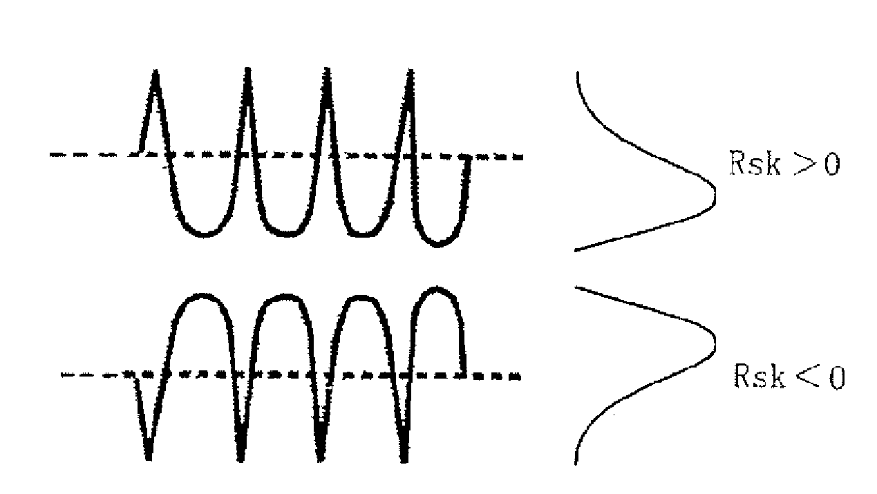
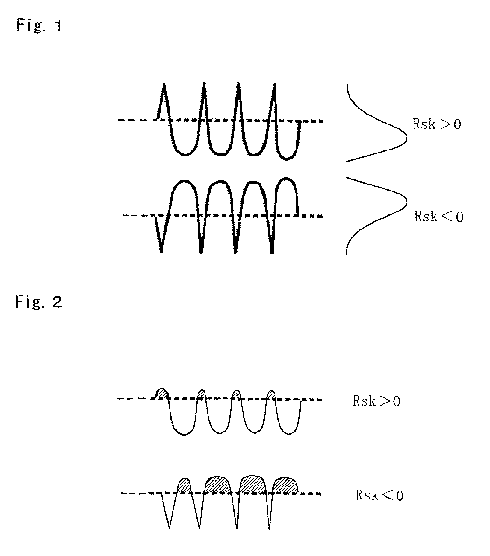
[0067] In this example, a coating of Al2O3, Y2O3 or Al2O3—Y2O3 composite oxide is directly formed on a surface of SUS304 substrate (40 mm in width×50 mm in length×7 mm in thickness) at a thickness of 120 μm by a plasma spraying process, and thereafter the surface thereof is subjected to the measurement of skewness value in the height direction of the coating surface by means of a roughness measuring meter of SURFCOM 1400D-13 (made by Tokyo Seimitsu Co., Ltd.) to distinct into coating of Rsk>0 and coating of Rsk<0. These coatings are subjected to or not to an irradiation of an electron beam to prepare test specimens.

[0068] With respect to these test specimens, the following items are examined by means of a reactive plasma etching apparatus having a plasma irradiating power of 80 W.

[0069] (1) Resistance to Plasma Etching

[0070] The surface of the test specimen is etched by flowing a mixed gas of CF4 gas (60 ml / min) and O2 gas (2 ml / min) into the plasma etching apparatus for 800 minu...

example 2

[0078] In this example, an undercoat of 80 mass % Ni-20 mass % Cr is formed on a surface of Al substrate (30 mm in width×50 mm in length×5 mm in thickness) at a thickness 80 μm and a coating of Al2O3, Y2O3 or Al2O3—Y2O3 composite oxide is formed thereon at a thickness of 250 μm through a plasma spraying process, respectively. Thereafter, Rsk value of roughness curve on the surface of the spray coating is measured by means of the aforementioned roughness meter to distinct Rsk>0 and Rsk<0, which are subjected to an irradiation of electron beam.

[0079] These spray coating specimens are subjected to plasma etching under the following conditions, the number of particles scatted by the etching action is compared with the number of particles adhered on a surface of a silicon wafer having a diameter of 3 inches arranged in the same apparatus. Moreover, the number of the adhered particles is examined by a surface inspection apparatus (magnifying glass), in which particle size of not less tha...

example 3

[0083] In this example, all test specimens used in the test of Example 2 for the resistance to plasma erosion are subjected to a thermal shock test. That is, the test specimen of the spray coating used in the test of Example 2 was subjected to the plasma erosion test under a corrosive environment containing a halogen gas, during which the corrosive halogen gas penetrated through pores of the top coat into the interior of the coating and may corrode the undercoat to easily peel off the top coat.

[0084] In the thermal shock test, the test specimen is heated in an electric furnace of 300° C. for 15 minutes and thereafter cooled in air of 24° C. for 20 minutes, and such an operation is repeated 10 times. Thereafter, the change of the top coat is visually observed. As a result, it has been confirmed that all test specimens shown in Table 2 hold a good resistance to thermal shock without causing the cracking of the top coat and the peeling of the coating.

[0085] The invention is applicabl...


PUM

PropertyMeasurementUnit
thicknessaaaaaaaaaa
particle sizeaaaaaaaaaa
roughnessaaaaaaaaaa

Abstract

A spray coated member having an excellent resistance to plasma erosion is produced by irradiating an electron beam to an outermost surface layer portion of a ceramic spray coated portion covering a surface of a substrate to form an electron beam irradiated layer.

Description

BACKGROUND OF THE INVENTION [0001] 1. Field of the Invention [0002] This invention relates to a member used in a thin film forming apparatus, a plasma treating apparatus or the like in a semiconductor processing process and a method of producing the same, and more particularly to a spray-coated member having an excellent resistance to plasma erosion, which is used as a member for a container used in the plasma processing under an environment containing a halogen compound, for example, a containing used in vacuum deposition, ion plating, sputtering, chemical deposition, laser precision working, plasma sputtering or the like, and a method of producing the same. [0003] 2. Description of Related Art [0004] In the semiconductor processing process, there is a step of forming a thin film of a metal, a metal oxide, a nitride, a carbide, a boride, a silicide or the like. In this step is used a thin film-forming apparatus for vacuum deposition, ion plating, sputtering, plasma CVD or the like ...

Claims


Application Information

Patent Timeline
Patent Type & Authority Applications(United States)
IPC IPC(8): G11B5/64
CPCC23C4/10C23C4/12C23C28/042C23C28/321Y10T428/26C23C28/345C23C28/3455Y10T428/24355C23C28/322
Inventor HARADA, YOSHIOTOGOE, KENICHIROKUSHIKI, FUJIO
Owner TOCALO CO LTD
Why Eureka
Try Eureka