Crystal firm, crystal substrate, and semiconductor device

a crystal firm and crystal substrate technology, applied in the direction of crystal growth process, polycrystalline material growth, semiconductor lasers, etc., can solve the problems of high-quality crystal film, large process requirements, and inability to achieve crystal film suitable for crystal growth, so as to reduce the dislocation density of the portion formed above the space and reduce the dislocation density of the upper layer on the substrate.

Inactive Publication Date: 2007-06-07
SONY CORP
View PDF10 Cites 17 Cited by
  • Summary
  • Abstract
  • Description
  • Claims
  • Application Information

AI Technical Summary

Benefits of technology

[0015] In a crystal film of an embodiment of the invention, spaces are provided on each end of dislocation, so the dislocation density in the portion formed above the spaces is reduced.
[0016] In another crystal film of an embodiment of the invention, a dislocation blocking portion is provided on each end of dislocation. As a result, the dislocation density in the portion formed above the spaces is reduced.
[0017] The crystal substrate and the semiconductor device of an embodiment of the invention comprise the crystal film of one of the embodiments of the invention, so the dislocation density on the upper layers on the substrate is reduced.

Problems solved by technology

However, a substrate suitable for crystal growth has not been achieved in the nitride III-V compound semiconductor.
However, obtaining a high quality crystal film has limitations and therefore, a technique for achieving a crystal film with lower threading dislocation density has been demanded.
However, most of the above-described methods require a mask formation step when forming the mask or seed crystal film and crystal growth more than once.
As a result, a lot of processes are required and this causes a problem with productivity.
Moreover, dislocations themselves are crooked and remain in the crystal.
This reveals that the conventional technique using the lateral growth has a limit of reduction in the dislocation density.
This has resulted in alignment problems and limits the size of the device.

Method used


Image

  • Crystal firm, crystal substrate, and semiconductor device
  • Crystal firm, crystal substrate, and semiconductor device
  • Crystal firm, crystal substrate, and semiconductor device

Examples


first embodiment

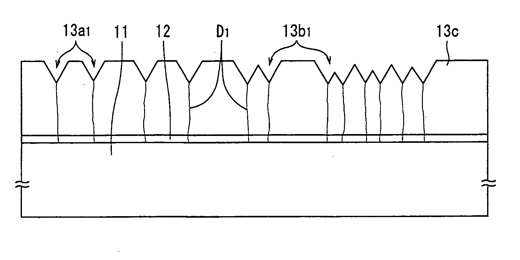
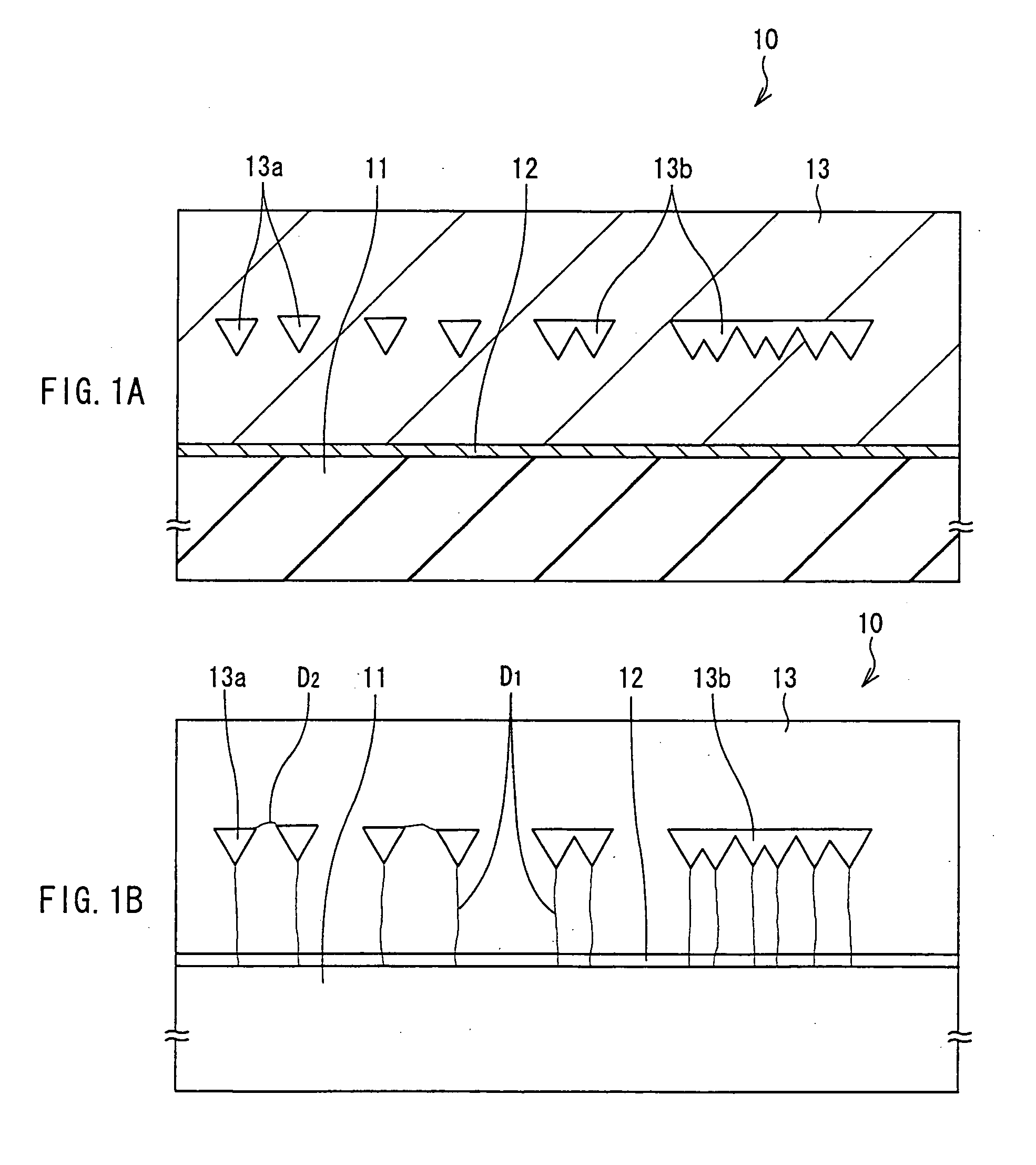
[0034]FIG. 1A shows a sectional structure of a crystal substrate 10 according to a first embodiment of the invention. FIG. 1B is a view showing dislocations of the crystal substrate 10 shown in FIG. 1A. In the crystal substrate 10, a crystal layer 13 is formed on a growth substrate 11 with a buffer layer 12 in between.

[0035] The growth substrate 11 is made of a crystalline material such as sapphire, silicon carbide (SiC), gallium nitride (GaN), gallium arsenide (GaAs), silicon (Si), a composite oxide of magnesium and aluminum (MgAl2O4; spinel), or a composite oxide of lithium and gallium (LiGaO2), and has a thickness of 400 μm, for example. The growth substrate 11 may be made of III-V compounds including at least one element selected from Group 3B elements and at least arsenic (As) and phosphorus (P) selected from Group 5B elements. The crystal substrate having dislocations are widely applicable as the growth substrate 11.

[0036] The buffer layer 12 is a core layer for growing the ...

second embodiment

[0056]FIG. 4A shows a sectional structure of a crystal substrate 20 of a second embodiment. FIG. 4B schematically shows dislocations of the crystal substrate 20 shown in FIG. 4A. The crystal substrate 20 has the same structure as the crystal substrate 10 of the first embodiment except that the crystal substrate 20 comprises a crystal layer 23 instead of the crystal layer 13 of the first embodiment.

[0057] The crystal layer 23 of the embodiment has spaces 23a and 23b like the spaces 13a and 13b of the first embodiment. However, a coat film 21 including, for example at least one of oxygen, nitrogen, fluorine or carbon is provided on the inner surface of the spaces 23a and 23b. The coat film 21 is preferably amorphous to avoid the growth of the crystal thereon. As the material of the coat film 21, a metal material such as aluminum (Al), gallium (Ga), indium (In), magnesium (Mg), zirconium (Zr) or titanium (Ti), silicon (Si) oxide, nitride, fluoride, and carbide are cited. The above met...

third embodiment

[0063]FIG. 6A shows a sectional structure of a crystal substrate 30 of a third embodiment. FIG. 6B schematically shows the crystal substrate 30 shown in FIG. 6A. The crystal substrate 30 has the same structure as the crystal substrate 10 of the first embodiment except that a crystal layer 33 is provided instead of the crystal layer 13 of the first embodiment. The crystal substrate 30 is fabricated as described hereinbelow.

[0064] First, as shown in FIG. 7, like the first embodiment, etch pits 33a1 and 33b1 are formed on a surface of a lower layer 33c. Subsequently, at least one of oxidation, nitridation, fuluoridation and carbonization is performed on the surface of the lower layer 33c including the etch pits 33a1 and 33b1 to form a surface treatment region 33c1. The surface treatment region 33c1 has a thickness of, for example 1 nm in the thickness direction. Specifically, the surface treatment region 33c1 made of oxide of Group 3B elements is formed by stopping the supply of the s...


PUM

PropertyMeasurementUnit
diameteraaaaaaaaaa
temperatureaaaaaaaaaa
thicknessaaaaaaaaaa

Abstract

A crystal foundation having dislocations is used to obtain a crystal film of low dislocation density, a crystal substrate, and a semiconductor device. One side of a growth substrate (11) is provided with a crystal layer (13) with a buffer layer (12) in between. The crystal layer (13) has spaces (13a), (13b) in an end of each threading dislocation D1 elongating from below. The threading dislocation D1 is separated from the upper layer by the spaces (13a), (13b), so that each threading dislocation D1 is blocked from propagating to the upper layer. When the displacement of the threading dislocation D1 expressed by Burgers vector is preserved to develop another dislocation, the spaces (13a), (13b) vary the direction of its displacement. As a result, the upper layer above the spaces (13a), (13b) turns crystalline with a low dislocation density.

Description

TECHNICAL FIELD [0001] The present invention relates to a crystal film and a crystal substrate, and a semiconductor device using the same, and specifically to a crystal film made of nitride III-V compounds, a crystal substrate and a semiconductor device such as a laser diode. RELATED ART [0002] In recent years, a nitride III-V compound semiconductor made of Group 3B elements such as aluminum (Al), gallium (Ga), indium (In) or the like and Group 5B elements including nitrogen (N) has drawn attention as a material capable of emitting light from a visible band ranging from green to blue to a near ultraviolet band. As a result, a semiconductor device such as a laser diode (LD) and a light emitting diode (LED) using the nitride III-V compound semiconductor is developed. Specifically, continuous oscillation is realized in the laser diode and an improvement in the crystalline of the nitride III-V compound semiconductor layer is demanded to realize longer operating life. [0003] However, a s...

Claims


Application Information

Patent Timeline
Patent Type & Authority Applications(United States)
IPC IPC(8): H01L29/06H01L33/00H01L31/00H01L29/739C30B25/18H01L21/20H01L21/205H01S5/323H01S5/343
CPCC30B25/02C30B25/183C30B29/403C30B29/406H01L21/0237H01L21/02458H01L21/02502H01L21/0254H01L21/0262H01L21/02639H01L21/0265H01L21/02538H01L21/20
Inventor MORITA, ETSUOMURAKAMI, YOUSUKEBIWA, GOSHIOKUYAMA, HIROYUKIDOI, MASATOOOHATA, TOYOHARU
Owner SONY CORP
Why Eureka
Try Eureka