

Thin film composite electrolyte
a composite electrolyte and thin film technology, applied in the direction of electrical equipment, basic electric elements, domestic applications, etc., can solve the problems of low ion flux, unsupported electrolyte tubes of the prior art can typically not be optimized for high flux, and cell made by conventional methods, etc., to achieve excellent bonding between the two layers, the effect of minimizing distortion
- Summary
- Abstract
- Description
- Claims
- Application Information
AI Technical Summary
Benefits of technology
Problems solved by technology
Method used
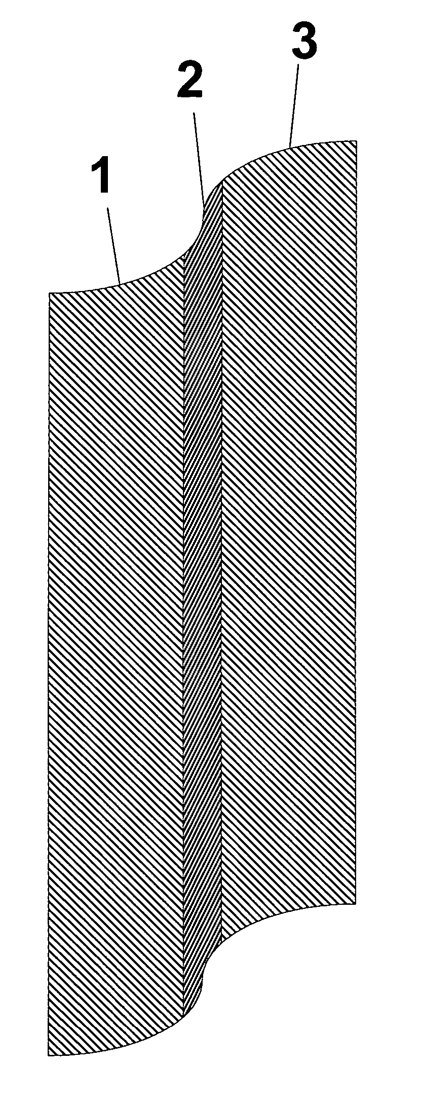
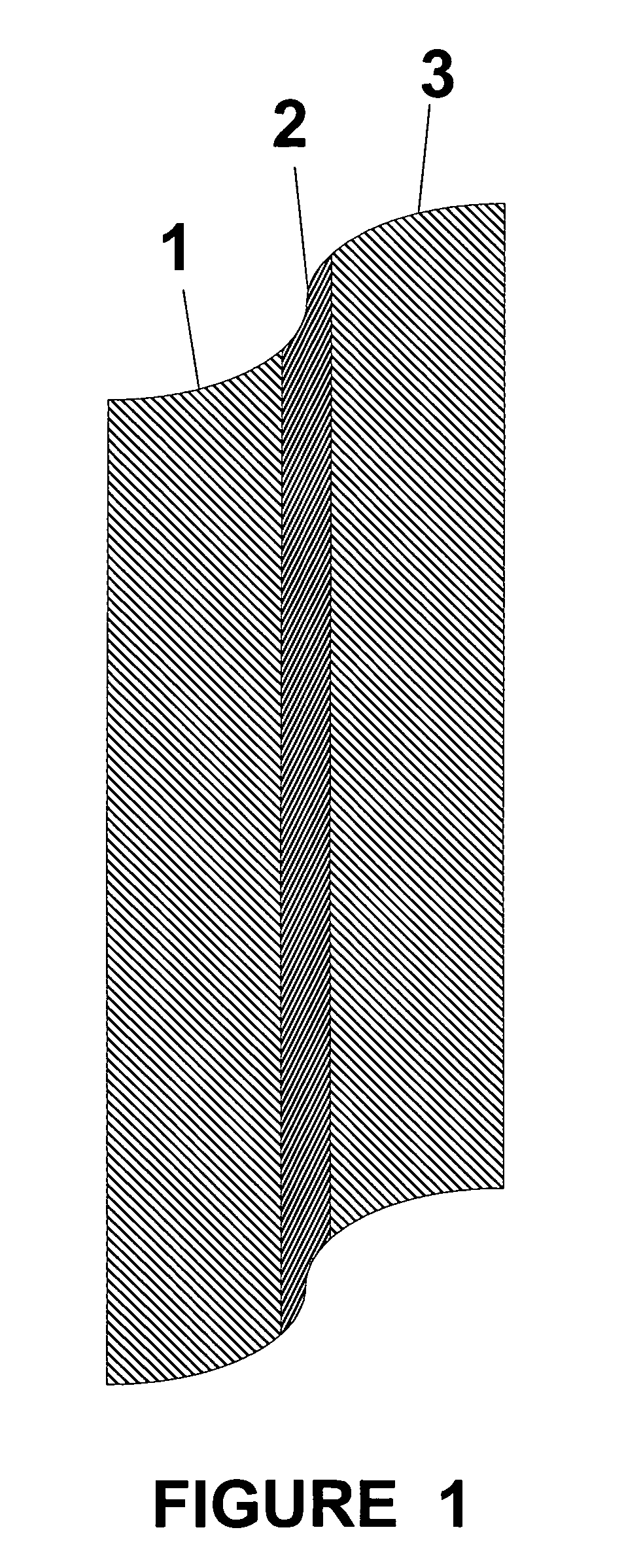
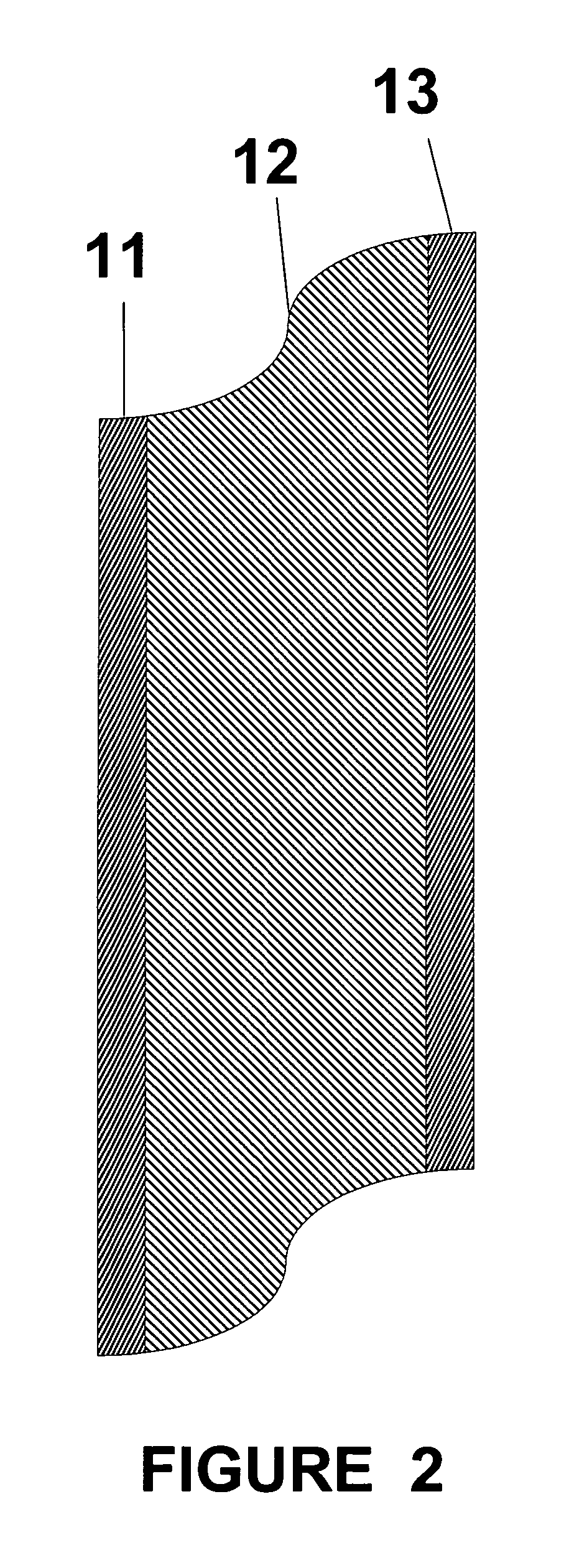
Image

Examples
example 1
β″-Al2O3 Powder Preparation, Dense Layer
[0049] Nanoparticulate β″-Al2O3 was purchased from TAL Materials Corporation (“TAL”) of Ann Arbor, Mich. Approximately 50 g of TAL β″-Al2O3 was attrition milled for two hours in isopropanol using 3 mm YSZ spherical media in order to break up agglomerates. The isopropanol was evaporated and the powder was dried at 120° C. for 24 hours for subsequent use in production of a slip for tape casting. Use of Nanoparticulate sized powders to form the thin dense layer allows the layer to densify at lower temperatures.
example 2
β″-Al2O3 Powder Preparation, Microporous Layer
[0050] A batch of β″-Al2O3 suitable for use in the microporous support layer was synthesized as follows. Approximately 85.65 g Bayerite alumina (UOP Versal B), 13.82 g Na2CO3 and 2.53 g MgCO3 were added to an attrition mill and milled in isopropanol using 3 mm YSZ spherical media for 1 hour to homogenize. The slurry was strained to remove the YSZ media and placed in an evaporating dish over a weekend to evaporate most of the isopropanol. The resulting powder was ground lightly with a mortar and pestle and loaded into a series of alumina crucibles, which were in turn placed in a drying oven at 100° C. to complete the drying process. Each crucible (with contents) was weighed while still warm to obtain the initial weight of the reactants. The crucibles were then placed in a muffle furnace, heated to 1,300° C. at 5° C. / min in air, held for 4 hours and cooled. Eight crucibles in all were used and the average weight loss per crucible was 36.0...
example 3
Slip Formation, Dense Layer
[0051] Into a small (˜1 pt) mill jar was added ˜215 g ¼″ YSZ cylindrical grinding media. To that was added 0.87 g menhaden fish oil (dispersant), 33.41 g mixed xylenes, 33.42 g anhydrous ethanol and 43.40 g hot (about 120° C.) (β″-Al2O3 from Example 1). The mill jar was sealed and the mixture milled on a roll mill at 60 rpm for 24 hours. To this was then added 3.48 g polyvinylbutyral (binder) and 1.75 g butyl benzyl phthalate (plasticizer). The mixture was further milled at 60 rpm for 24 hours. The slip was then strained to remove grinding media and de-aired under a slight vacuum (˜680 torr) to remove entrained air bubbles. This slip was designated SLIP-026.
PUM
| Property | Measurement | Unit |
|---|---|---|
| Temperature | aaaaa | aaaaa |
| Temperature | aaaaa | aaaaa |
| Temperature | aaaaa | aaaaa |
Abstract
Description
Claims
Application Information