
Integrated solar liquid heater, distiller and pasteurizer system

a solar liquid heater and distiller technology, applied in vacuum distillation separation, lighting and heating apparatus, separation processes, etc., can solve the problems of system failure to take full advantage of the heat pipe concept, system not designed to take advantage of evacuated solar collectors and relatively high efficiency associated, and less efficient solar systems in the field of integrated solar heating and solar distilling systems. , to achieve the effect of enhancing the capacity of the tank to deform elastically, reducing the formation of scale, and increasing the density of stored energy

Inactive Publication Date: 2007-08-23
TECHNOSON PUERTO RICO
View PDF9 Cites 40 Cited by
  • Summary
  • Abstract
  • Description
  • Claims
  • Application Information

AI Technical Summary

Benefits of technology

[0021] Accordingly, several objects and advantages of my invention are durability, low cost, low maintenance, high efficiency, operation at high temperatures, compactness, self cleaning, modularity, collapsibility, versatility and multi-functionality, resistance to corrosion, fouling and hurricanes. A novel implementation of solar vacuum tube collector, a multiple effect heat storage system and a distillation column achieves a major advantage of my design. The advantage is its capacity to simultaneously heat, distill, and pasteurize water or any other liquid medium without major equipment reconfiguration and by equipment that can be delivered in kit form and mass produced at low manufacturing costs. SUMMARY OF THE INVENTION
[0024] A preferred embodiment of my solar heater-distiller also includes a composite heat and distillate storage system. The system includes a covered, insulated, cylindrical tank. The tank contains a heat storage medium, such as distilled water, and can include a phase change material to increase the density of the stored energy. The heat storage system includes a means of removal of the stored heat energy, or heat exchanger, for utilization in heating an external flow of water, such as tap water running into the hot water pipe system of a house. The longitudinal walls of the cylindrical tank are formed with a multiplicity of substantially parallel troughs or ribs that run around the tank circumference. This geometry will enhance the capability of the tank to deform elastically under pressure and therefore transmit the strain and stress generated by internal pressures to the external composite structure conformed by the insulation material and the outside cover of the heat storage system, sharing the loads in a cooperative way. This composite construction of a solar heat storage system is unique and allows for the economical use of more exotic materials such as stainless steels or high temperature plastics that are resistant to corrosion. Additionally, the ribbed construction of the tank walls decreases the formation of scale and increase heat transfer by enhancing fluid turbulence. Furthermore, the continuous expansion and contraction of the tank walls help to loosen any scale that might form so that it can be easily removed during maintenance. At the mid point of the tank's longitudinal axis, a steam intake bent pipe is placed to receive steam from the distillation column through an disconnectable universal union. The universal union is used to connect the storage tank to the distillation column for vapor and heat transfer. The steam or vapor will condense into distillate and will release latent heat inside the storage tank. The latent heat will be absorbed by the distillate inside the storage tank and transferred to the external water flow for further use.
[0025] In one preferred embodiment, the evacuated glass solar collector consists of a multiplicity of substantially parallel linear evacuated glass solar collectors. Each evacuated collector consists of an external glass vacuum envelope with circular cross section, and an internal concentric glass tube for absorbing the incident solar radiation. The internal surface of the absorbing glass tube is first sputtered with a layer of infrared radiant material and then with a layer of a selective solar radiation absorber. The glass absorbing tubes have one end closed in the vacuum and the other end with opening external to the vacuum. This open end is sealed to the glass vacuum envelope. An additional glass vacuum envelope insert is placed inside each glass absorbing tube. The various glass parts of the evacuated glass solar collector are formed from the same glass or glass with substantially the same thermal expansion. This allows much easier and much lower cost sealing of the various parts of the evacuated glass solar collector. The open end of the vacuum tube is inserted into the lateral holes of the distillation column and releasably sealed by silicon rings. The distilland will fill the vacuum tube collector and boil creating a turbulent liquid and vapor mass flow with self-cleaning characteristics that will help mitigate and slow down salt precipitation inside the distillation column subassembly.
[0026] The fouling-corrosion resistant integrated solar heater-distiller-pasteurizer of this invention is unique in its choice of features for its design, which optimize its performance while minimizing its extended cost. The unique integration, simplicity, versatility and modularity of this design lead to low initial and extended cost. The choice of design characteristics, which minimize heat loss and maximize solar energy collection and self-cleaning lead to a highly efficient solar heater-distiller-pasteurizer which can reliably operate at temperatures suitable for distillation and pasteurization processes. Further, the functional and structural integration of the composite heat storage system, the distillation column-reflector-bracket assembly, and the evacuated glass solar collector into one compact unit is very important, since this leads to the economical use of corrosion and fouling resistant materials and assembly processes at much lower cost, and a more efficient, reliable, flexible, and versatile operation.
[0027] The present invention provides an integrated, and yet simplified, solar heating-distilling-pasteurizing system of greatly improved efficiency, proven commercial feasibility, lower initial and operational costs, improved reliability, better performance in different climates, improved durability, and easier fabrication and distribution which form the essence of this invention.

Problems solved by technology

Further, the prior art solar systems are less efficient and have a high cost relative to the integrated solar system presented here, either by lacking certain design features which are important for efficient solar systems, or by lacking design or production features needed to achieve low cost, or both of these reasons.
In the prior art, the system of U.S. Pat. No. 4,505,261 is not designed to take advantage of evacuated solar collectors and the relatively high efficiency associated with them.
This system fails to take full advantage of the potential of the heat pipe concept.
However, the above-described system does not use evacuated (vacuum) glass tubes for increased efficiency.
Therefore, it is not suited for sustaining the high temperatures desired for pasteurization and distillation processes.
Therefore, this design uses the potential for structural and functional integration in a very limited way.
However, this design lacks adequate structural integrity.
Despite the above substantial advantages over other prior art, heretofore it has not been possible to fully utilize the potential of the integrated reservoir, heat pipe, and the extended costs.
None of the above-described designs use corrosion and / or fouling mitigating measures in the reservoir.
Despite achieving a higher level of functional integration relative to prior art, the above designs still lack the high level of functional and structural integration that allow the economical use of more exotic materials such as, but not limited to, stainless steels or special temperature resistant glass.
In short, while incorporation of the heat pipe and evacuated collector technology into integrated and / or modular solar heating systems represent an advance in passive solar energy technology, the potential of such integration for combined simplicity, durability, ease of maintenance, efficiency, and low initial and extended cost has not been fully realized.
The inherent design problems of many types of solar stills are described.
However, basin stills and tilted still designs have been plagued by multiple deficiencies.
Basin and tilted stills produce efficiently during the summer months but inefficiently during the winter months.
This is because basin stills are very susceptible to heat loss into a low temperature environment and to the shallow incidence angle of solar radiation at that time of the year.
Another major problem of basin and tilted stills is the accumulation of evaporative salt deposits and algae growth.
These salts diminish the still efficiency and algae growth will contaminate the distilled water and promote bacteria growth.
The accumulation of evaporative salts and algae growth has to be periodically flushed or scrubbed, requiring substantial maintenance efforts and costs.
Another major problem of basin and tilted stills is the insulation techniques implemented by previous art.
The method of insulation is inferior to that insulation provided by air evacuation or partial vacuum inside insulating volumes.
Because of their geometry, it is very difficult to implement vacuum insulation techniques in basin and tilted still designs.
Because basin stills and tilted stills have to be periodically opened for flushing and cleaning, another major problem of basin and tilted stills is the difficulty to effectively seal the linear surfaces where the undersurface of the transparent still cover contacts the planar top surfaces of the walls enclosing the evaporation chamber.
The difficulties will decrease the distilling efficiency and will promote vapor leaks, low temperatures, distillate contamination, bacterial growth and high manufacturing costs.
Major problems of the wick matting include: (1) Absorptive capacity is inadequate.
Multiple effect solar stills are more efficient and productive, they are also more complicated and costly to construct and extra work is required to keep them clean and in adjustment.
Prior art has not been able to implement cost effective multiple effect techniques into solar stills.
As a result, the multiple effect solar still is not considered to be the most practical for everyday use.
The proposed solar distiller improvements described in U.S. Pat. No. 4,686,961 and most of those proposed by other prior art do not utilize the benefits of the all glass vacuum tube collectors, operating at low temperatures and low efficiencies.
The distiller improvements have failed to reach the market because of increased manufacturing and operating costs associated to the increased mechanical complexity of the designs.
None of the solar stills described in the prior art can efficiently provide simultaneous water heating, distilling, and pasteurizing for a typical domestic application.
Despite achieving a higher level of efficiency relative to prior art, the above designs still lack a high level of functional and structural integration that allows the economical use of more exotic materials such as, but not limited to, stainless steels or special temperature resistant glass.
In short, while incorporation of the heat pipe and evacuated collector technology into integrated and / or modular solar heating and distilling systems represent an advance in passive solar energy technology, the potential of such functional and structural integration for combined simplicity, durability, ease of maintenance, efficiency, and low initial and extended cost has not been fully realized.

Method used


Image

  • Integrated solar liquid heater, distiller and pasteurizer system
  • Integrated solar liquid heater, distiller and pasteurizer system
  • Integrated solar liquid heater, distiller and pasteurizer system

Examples


Embodiment Construction

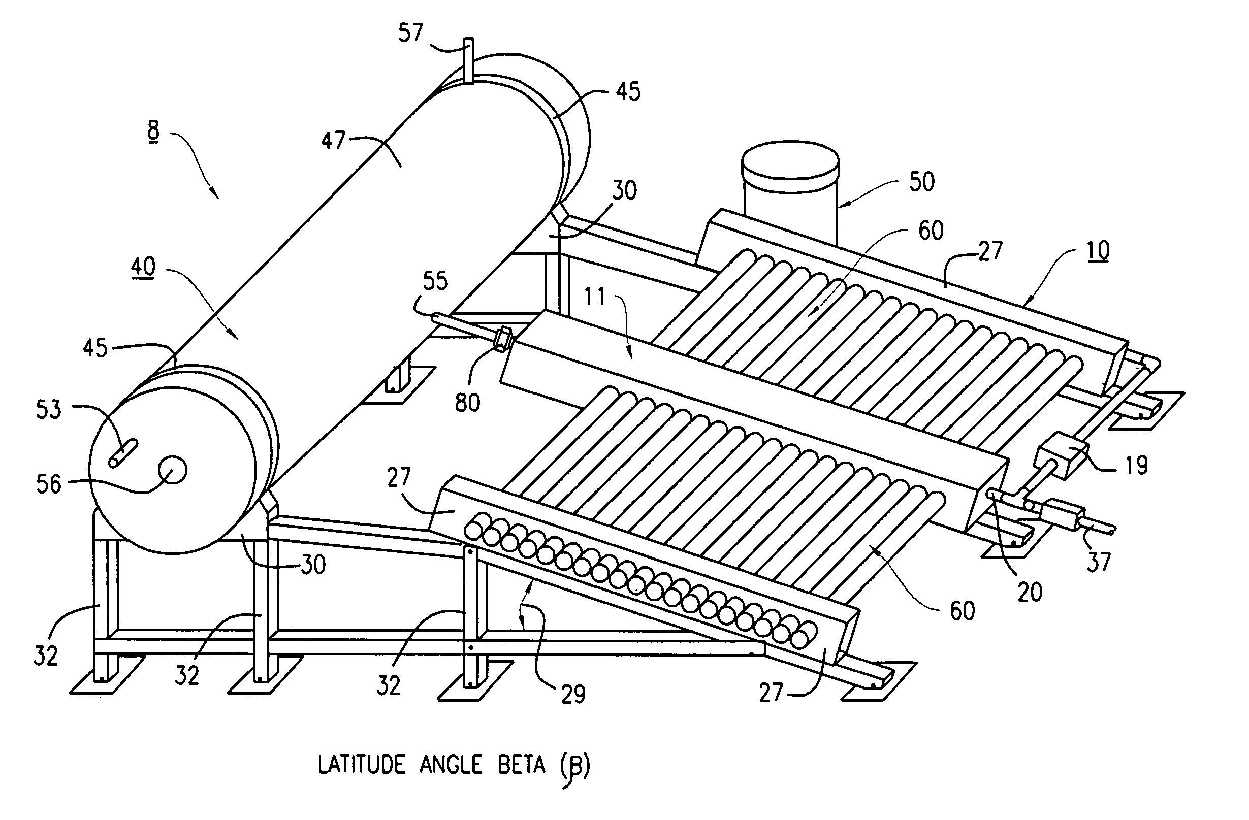
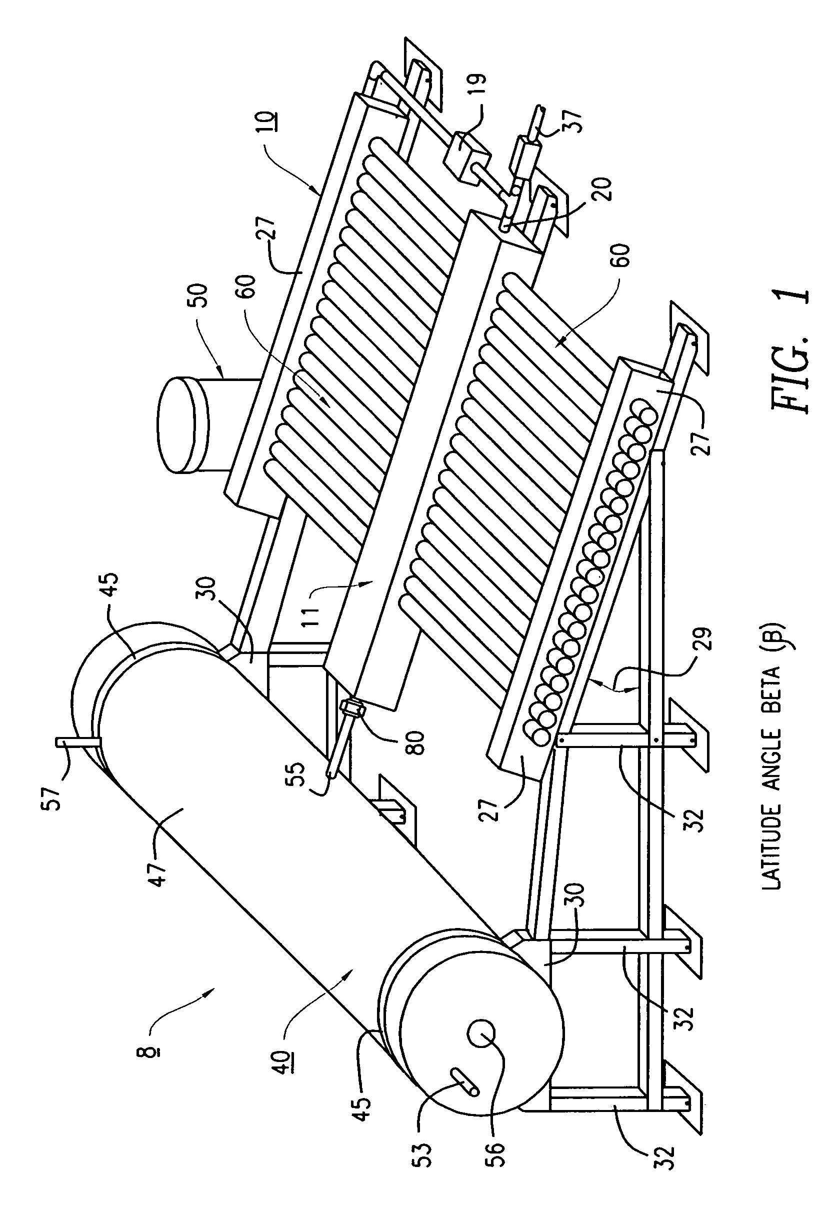
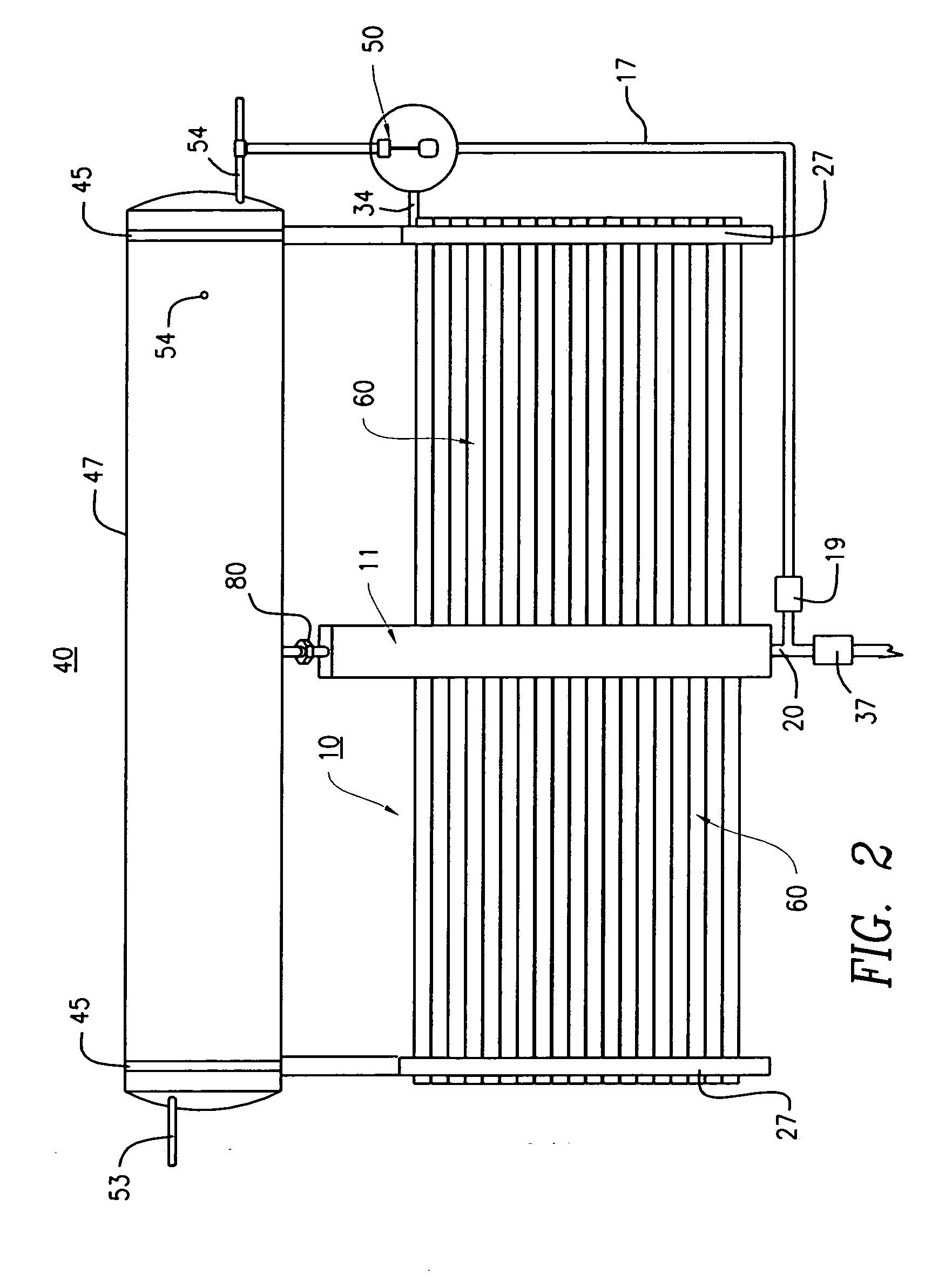
[0048] The integrated solar heater, distiller and pasteurizer system 8 and its component parts of the preferred embodiment of the present invention are represented in detail by FIGS. 1 through 19 of the patent drawings. The combined solar heater, distiller and pasteurizer system 8 is used for the heating (ΔH) of a liquid medium 21 such as water; alcoholic beverages such as wine, whiskey, rum and the like; milk and the like, in order to remove impurities, particulates and precipitates from the liquid medium 21. This system includes a distillation column-reflector-bracket assembly 10, a composite distillate and heat storage assembly 40, and at least one evacuated glass solar collector 60 having selective absorption.

[0049]FIGS. 1 and 2 illustrates the distillation column-reflector-bracket assembly 10 that includes the distillation column subassembly 11 that is a principal part of this invention. As shown in FIGS. 5 through 7, the distillation column subassembly 11 is used for the heat...


PUM

PropertyMeasurementUnit
Angleaaaaaaaaaa
Angleaaaaaaaaaa
Angleaaaaaaaaaa

Abstract

The solar heating, distilling, and pasteurizing system of this invention comprises an integrated distillation column-reflector-bracket assembly, a heat storage system of composite construction, and at least one evacuated glass solar collector having selective absorption. The distillation column subassembly is filled with the fluid medium to be boiled which flows into the solar vacuum tube collectors where an evaporation process takes place. A float valve mechanism mounted to the frame automatically maintains the correct liquid level inside the distillation column. The height of float valve mechanism is adjustable by means of an adjustable float bracket. The distillation column subassembly collects and concentrates the steam or vapor generated inside the attached evacuated glass solar collector tubes. The column also separates the vapor from the boiling liquid medium and conducts the vapor into a heat and distilled fluid storage system. The reflector-bracket subassembly has a reflecting panel made from at least one sheet of reflective material typically flat or formed into a plurality of substantially parallel linear troughs shaped to concentrate solar radiation ideally. This reflector also acts as a means of further stress and strain distribution and dissipation into the structural elements of the bracket subassembly.

Description

FIELD OF THE INVENTION [0001] The present invention relates to a combined and integrated solar heating and solar distilling system. More particularly, to a modular and integral solar heating and distilling system which uses a composite heat storage system, a distillation column, all glass evacuated glass solar collector, a water feed and level control system, and a reflector-support bracket. BACKGROUND OF THE INVENTION [0002] Solar water heating systems are well established in the art and numerous designs for solar thermal systems have appeared over the years in patents and in the published literature. The so-called water thermosyphon may well be the prevalent passive solar water heating system in terms of worldwide usage. [0003] Most of these designs apparently operate properly, although some are more highly preferred by virtue of lower cost, greater durability, and / or higher efficiency. A major problem has been the extended cost of this energy relative to the cost from other sourc...

Claims


Application Information

Patent Timeline
IPC IPC(8): B01D3/42
CPCB01D1/0035B01D1/04C02F1/14B01D3/42B01D3/10Y02E10/44Y02E10/47Y02A20/212F24S60/30F24S25/10F24S10/45F24S60/10
Inventor GARCIA, EDUARDOVAIDA, GEORGE
Owner TECHNOSON PUERTO RICO
Learn More