Circuit Board, Method Of Manufacturing Circuit Board, And Display Device Having Circuit Board

a manufacturing method and circuit board technology, applied in the field of circuit board, can solve the problems of increasing the manufacturing cost of the electronic device board, unable to obtain the required wiring width, and extremely low utilization efficiency of wiring materials, and achieve the effect of fine wiring formation and sufficient contras

Inactive Publication Date: 2007-09-13
OHMI +1
View PDF7 Cites 9 Cited by
  • Summary
  • Abstract
  • Description
  • Claims
  • Application Information

AI Technical Summary

Benefits of technology

[0019] Therefore, an object of this invention is to provide a method of manufacturing a circuit board that can give sufficient contrast to wettability of a liquid conductive material between a partition member and an insulating substrate without degrading the partition member, thereby realizing fine wiring formation by an inkjet method.

Problems solved by technology
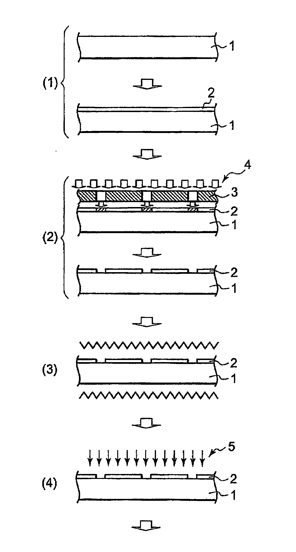
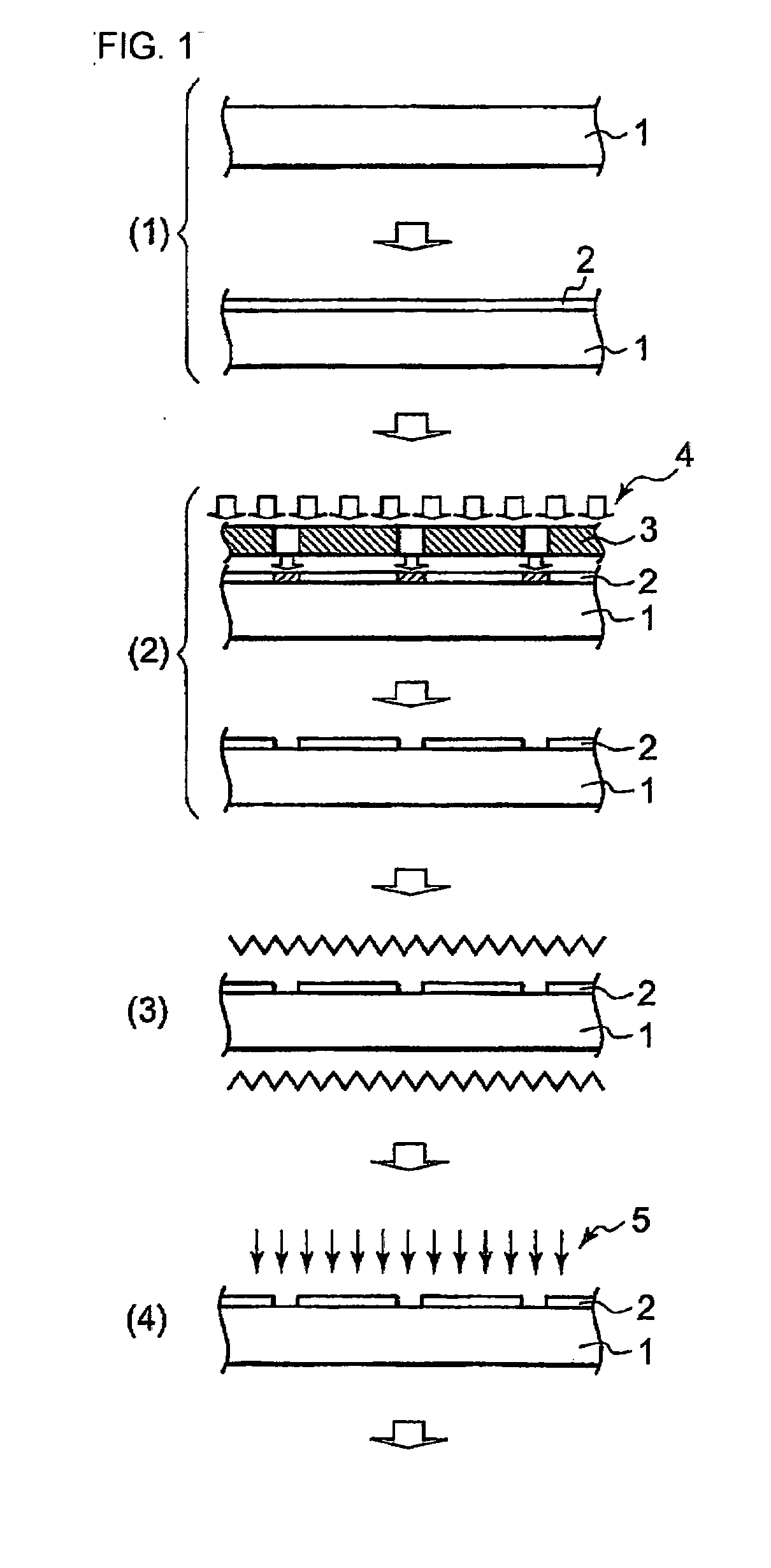
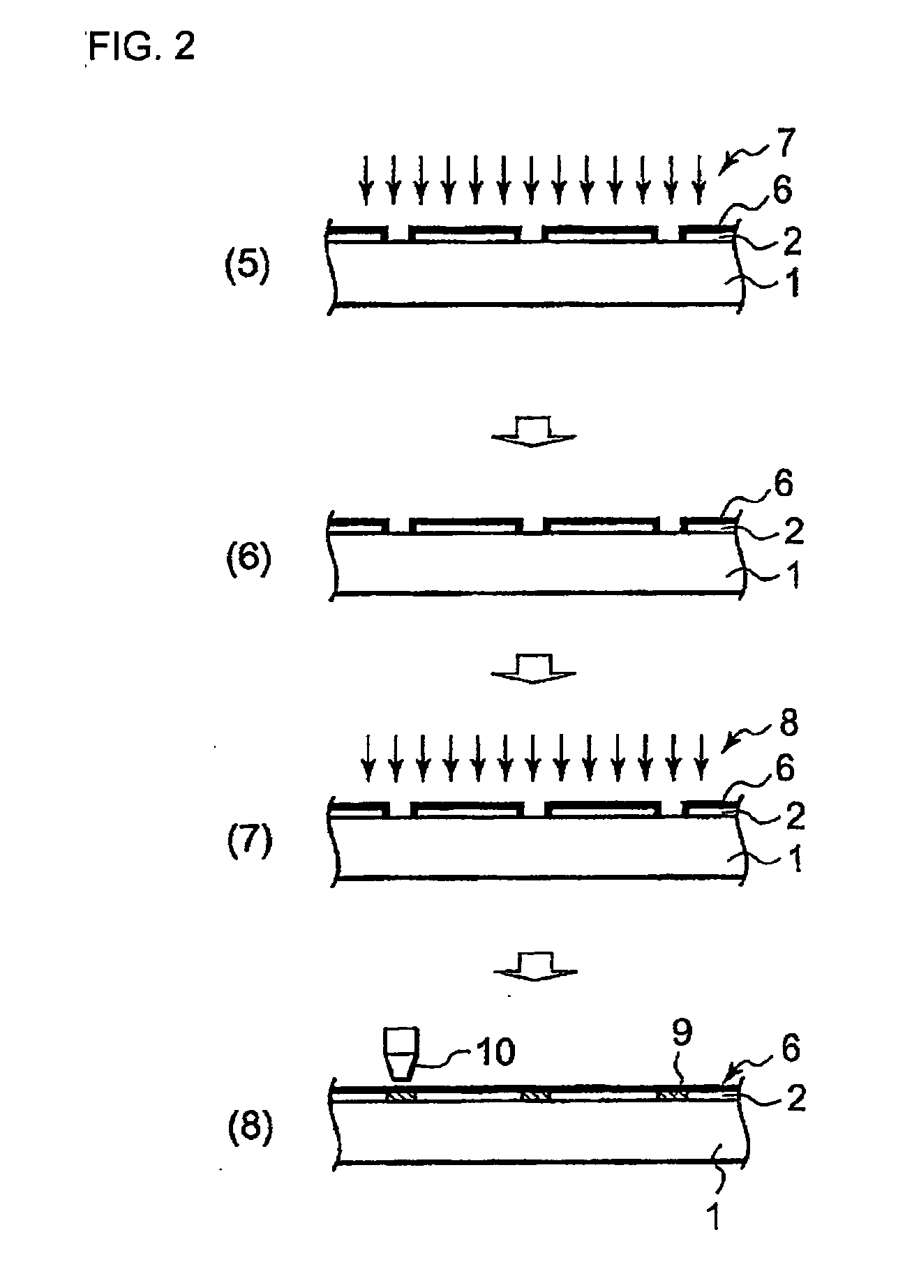
Accordingly, the utilization efficiency of the wiring material is extremely low, which is a main cause for increasing the manufacturing cost of the electronic device board.
In this event, when the partition member has liquid affinity or wettability with respect to the liquid conductive material, the liquid conductive material is pulled by the partition member so as to be wetted over the outside of the partition member and therefore it is not possible to obtain a required wiring width finally.
This causes disconnection in the case of wiring.
However, when forming a wire having a fine width of 10 μm or less by the inkjet method, there is a problem that the liquid material overflows or is excessively wetted over because of an insufficient difference in liquid affinity / repellency between the upper portion of the partition member and the bottom surface of the region surrounded by the partition member.
Further, since a plasma apparatus itself is quite complicated, there is a problem that the production line becomes quite complicated in the case of the actual manufacture of electronic device circuit boards.
However, there is a problem that since the fluorine compound is formed also at the portion which should primarily be made liquid-affinitive, the effect is lowered.
As a result, there is a problem that the value of liquid repellency at the side wall portion is low relative to the value of liquid repellency at the bottom surface of a pattern and therefore, the receptability of the liquid conductive material for fine wiring formation is poor.

Method used


Image

  • Circuit Board, Method Of Manufacturing Circuit Board, And Display Device Having Circuit Board
  • Circuit Board, Method Of Manufacturing Circuit Board, And Display Device Having Circuit Board
  • Circuit Board, Method Of Manufacturing Circuit Board, And Display Device Having Circuit Board

Examples


examples

[0128] Hereinbelow, examples of this invention will be described. This invention is not limited to the following examples. Analysis values in the following examples and comparative examples are each derived by rounding to the nearest whole number and “parts” represents “weight parts”.

[0129] The analysis conditions in the following examples and comparative examples are as follows.

[0130] (Test 1) Thermal Desorption Spectroscopy (Hereinafter Abbreviated as “TDS Analysis”) [0131] Apparatus: EMD-WA1000S / W manufactured by Denshi Kagaku Co., Ltd.

[0132] (Test 2) Fourier Transform Infrared Spectroscopy (Hereinafter Abbreviated as “FT-IR Analysis”) [0133] Apparatus: Spectrum One manufactured by Perkin Elmer Corporation

[0134] (Test 3) Cavity Ring-Down Spectroscopy (Hereinafter Abbreviated as “CRDS Analysis”) [0135] Apparatus: MTO-1000H2O manufactured by Tiger Optics, Inc.

(Test 4) Contact Angle Measurement [0136] Apparatus: CA-D manufactured by Kyowa Interface Science

[0137] Using tetrade...

manufacturing example 1

[0143] [Adjustment of Thermosetting Photosensitive Resin Composition (Positive-Type)]

[0144] 62.5 parts of 8-hydroxycarbonyltetracyclo[4.4.0.12,5.17,10]

[0145] dodeca-3-ene, 37.5 parts of N-phenyl-(5-norbornene-2,3-dicarboximide), 1.3 parts of 1-hexene, 0.05 parts of 1,3-dimethylimidazolidine-2-iliden(tricyclohexylphosphine)benzylideneruthenium dichloride, and 400 parts of tetrahydrofuran were put in a pressure-proof reactor made of a nitrogen-substituted glass and reacted at 70° C. for 2 hours while being stirred, thereby obtaining a polymer solution A (solid concentration about 20%).

[0146] Part of the polymer solution A was moved into an autoclave with a stirrer and reacted, with hydrogen dissolved, at 150° C. and a pressure of 4 MPa for 5 hours, thereby obtaining a polymer solution B (solid concentration: about 20%) containing a hydrogenated polymer (hydrogenation ratio 100%).

[0147] A heat-proof container containing 100 parts of the polymer solution B with 1 part of activated car...

manufacturing example 2

[0149] [Adjustment of Thermosetting Photosensitive Resin Composition (Negative-Type)]

[0150] 300.0 parts of methyltrimethoxysilane, 47.5 parts of ion-exchanged water having an electrical conductivity of 8×10⁻⁵ S·cm−1, and 0.1 parts of oxalic acid were put into a container with a stirrer and, then, methyltrimethoxysilane was hydrolyzed by heating and stirring under the conditions of 60° C. and 6 hours. Then, after adding 1,000 parts of propyleneglycolmonomethylether into the container, the ion-exchanged water and methanol secondarily produced by the hydrolysis were removed by the use of an evaporator, thereby obtaining a solution in which the solid content was adjusted to 25 wt %.

[0151] 400 parts of the foregoing solution and 2.0 parts of phenyl, 4-(2′-hydroxy-1′-tetradecaoxy)phenyliodonium-p-toluenesulfonate serving as a radiation-sensitive acid forming agent were uniformly mixed and dissolved, and then filtered through a membrane filter having a pore size of 0.2 μm, thereby obtaini...


PUM

PropertyMeasurementUnit
widthaaaaaaaaaa
wavelengthaaaaaaaaaa
temperatureaaaaaaaaaa

Abstract

A circuit board manufacturing method includes formation of a thermosetting photosensitive resin film on an insulating board by a spin coat method and the like, exposure of the photosensitive resin film to radiation rays such as ultraviolet rays, development with a developer or by etching, heat-hardening of the photosensitive resin film, oxygen plasma treatment or ultraviolet treatment if required, adjustment of a water quantity in the photosensitive resin film by drying the resin film, exposure in a fluorine gas atmosphere, anneal treatment, and then immersion of the resin film in a fluorinated acid chemical.

Description

TECHNICAL FIELD [0001] This invention relates to a circuit board adapted for electrical / electronic use, a method of manufacturing the circuit board, and a display device having the circuit board. BACKGROUND ART [0002] A board for electronic devices and apparatuses is formed by disposing, on an insulating substrate such as a glass or resin substrate or on a substrate of which at least the surface is made of an insulator, many thin film transistors and a single electrical wiring layer or multiple electrical wiring layers adapted for connection between those transistors or between the transistors and a power supply or input / output terminals. [0003] As one of typical embodiments of the board for electronic devices and apparatuses, there is a display device such as an active matrix liquid crystal display device or organic EL display device. The entire board including scan lines, signal lines, and so on is also called an active matrix board, which is constituted by forming, on the surface...

Claims


Application Information

Patent Timeline
Patent Type & Authority Applications(United States)
IPC IPC(8): H05K3/10G02F1/1362G03F7/40H01L21/48H05B33/14H05K3/00H05K3/12H05K3/18
CPCG02F2001/136295G03F7/40H01L21/481H05K3/0023H05K3/0073Y10T29/49155H05K3/1258H05K3/184H05K2203/0568H05K2203/087H05K2203/095H05K3/1241G02F1/136295G02F1/13H05K3/10
Inventor OHMI, TADAHIRONII, KEIICHISUZUKI, TERUHIKOKATO, TAKEYOSHI
Owner OHMI
Why Eureka
Try Eureka