

Novel Compound and Organic Electronic Device Using the Same
a technology of organic electronic devices and compound, applied in nanoinformatics, applications, instruments, etc., can solve the problems of affecting the use environment, physical and chemical deterioration, and so-called active devices using active functions generated by flowing currents to materials, and achieves the effect of longer life and higher sensitivity
- Summary
- Abstract
- Description
- Claims
- Application Information
AI Technical Summary
Benefits of technology
Problems solved by technology
Method used
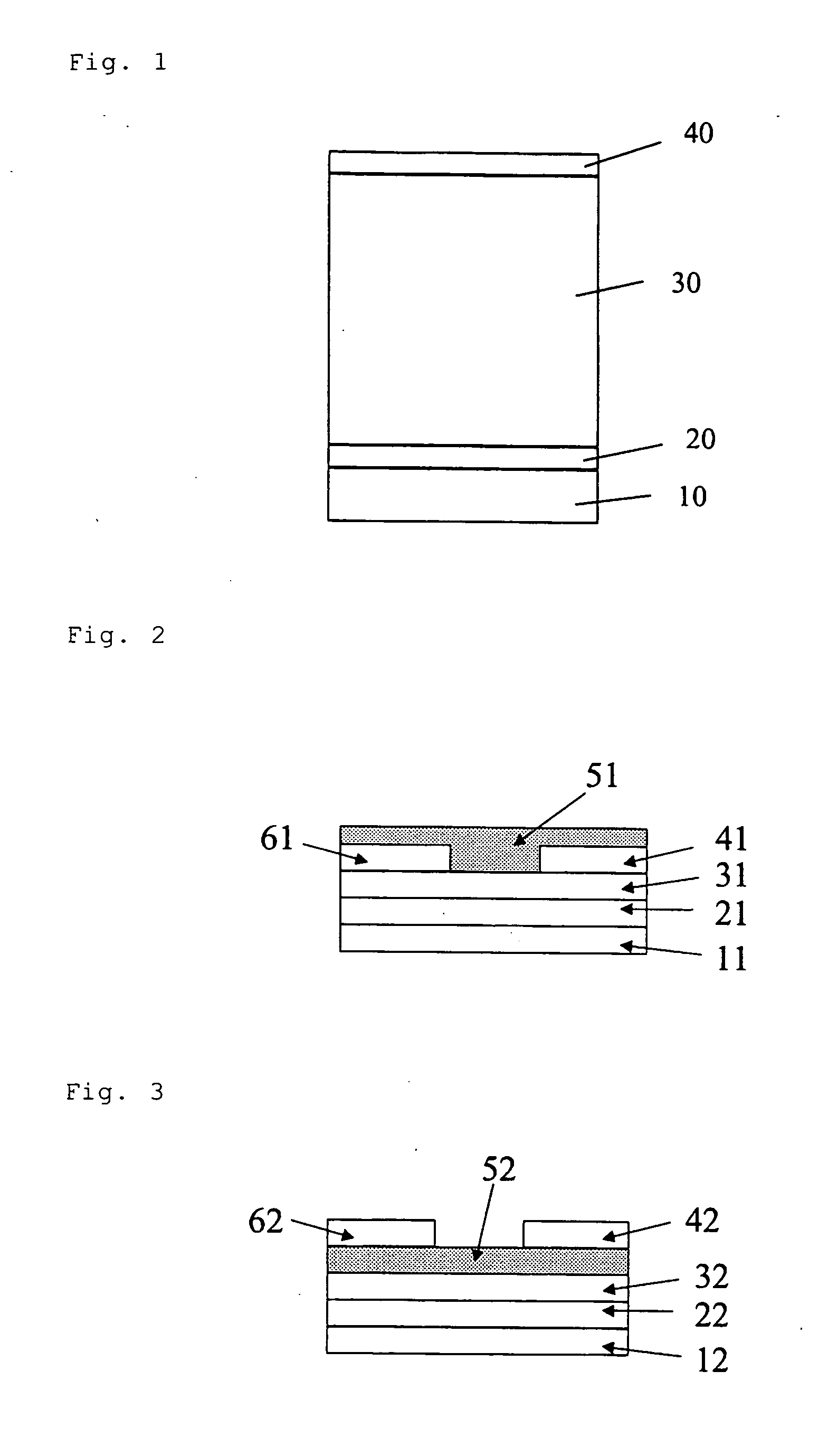
Image


Examples
example 1
[0212]
First Step: Synthesis of Naphthalene Monoimide Derivative (1-1)
[0213] 8.0 g of a naphthalene-1,4,5,8-tetracarboxylic dianhydride and 50 ml of dehydrated DMF were introduced into a reactor. The reactor was heated to reflux. 3.85 g of 2-ethylhexylamine dissolved in 30 ml of dehydrated DMF was added dropwise into the reactor while stirring. After the dropwise addition was completed, the resultant was further heated to reflux for 6 hours. After cooling, the resulting mixture was concentrated under a reduced pressure. The residue was diluted with toluene and the insoluble portion was filtered off. The filtrate was purified by silica gel column chromatography to obtain the desired naphthalene monoimide derivative (1-1). Yield: 3.89 g.
Second Step: Synthesis of Naphthalene Monoimide Monohydrazone Derivative (1-2)
[0214] 12.0 g of a naphthalene-1,4,5,8-tetracarboxylic dianhydride and 60 ml of dehydrated DMF were introduced into a reactor. The reactor was heated to reflux. 5.78 g of...
example 2
[0218]
First Step: Synthesis of Naphthalene Monoimide Derivative (2-1)
[0219] 27.0 g of a naphthalene-1,4,5,8-tetracarboxylic dianhydride and 250 ml of dehydrated DMF were introduced into a reactor. The reactor was heated to reflux. 9.0 g of 3-aminopentane dissolved in 100 ml of dehydrated DMF was added dropwise into the reactor for 30 minutes while stirring. After the dropwise addition was completed, the resultant was further heated to reflux for 6 hours. After cooling, the resulting mixture was concentrated under a reduced pressure. The residue was diluted with toluene and the insoluble portion was filtered off. The filtrate was purified by silica gel column chromatography to obtain the desired product of a light yellow monoimide derivative (2-1). Yield: 13.3 g.
Second Step: Synthesis of Naphthalene Monoimide Monohydrazone Derivative (2-2)
[0220] 10.0 g of the naphthalene monoimide derivative (2-1) obtained as above and 100 ml of dehydrated DMF were introduced and dissolved. Then...
example 3
[0223]
First Step: Synthesis of Naphthalene Monoimide Derivative (3-1)
[0224] 42.0 g of a naphthalene-1,4,5,8-tetracarboxylic dianhydride and 400 ml of dehydrated DMF were introduced into a reactor. The reactor was heated to reflux. 18.9 g of 2-heptylamine dissolved in 100 ml of dehydrated DMF was added dropwise into the reactor over 50 minutes while stirring. After the dropwise addition was completed, the resultant was further heated to reflux for 6 hours. After cooling, the resulting mixture was concentrated under a reduced pressure. The residue was diluted with toluene and the insoluble portion was filtered off. The filtrate was purified by silica gel column chromatography to obtain the desired product of a light yellow monoimide derivative (3-1). Yield: 25.3 g.
Second Step: Synthesis of Naphthalene Monoimide Monohydrazone Derivative (3-2)
[0225] A naphthalene monoimide monohydrazone derivative (3-2) was produced in the same manner as in the second step of Example 2.
Third Step...
PUM
| Property | Measurement | Unit |
|---|---|---|
| drive voltage | aaaaa | aaaaa |
| temperature | aaaaa | aaaaa |
| wavelength | aaaaa | aaaaa |
Abstract
Description
Claims
Application Information