Method for manufacturing an optical film having a convexoconcave structure, optical film, wire grid polarizer and retardation film

Inactive Publication Date: 2007-11-01
KONICA MINOLTA OPTO
View PDF1 Cites 50 Cited by
  • Summary
  • Abstract
  • Description
  • Claims
  • Application Information

AI Technical Summary

Benefits of technology

[0015]The present invention provides a method for high-precision and high-speed manufacturing of an optical film provided with a microscopically convexoconcave structure over a large

Problems solved by technology

In the thermo-imprint technique, it is difficult to press a large-area mold against the sheet at a uniform force, and this has been an obstacle to stable production.
Further, to make a model of a microscopical structure on the order of submicrons with satisfactory transferability, long transfer time is required.
This means a lower productivity.
High-speed transfer will be difficult especially when a microscopical structure on the order of submicrons is to be transferred.
This method also has difficulties with high-speed production by a roll mold an

Method used


Image

  • Method for manufacturing an optical film having a convexoconcave structure, optical film, wire grid polarizer and retardation film
  • Method for manufacturing an optical film having a convexoconcave structure, optical film, wire grid polarizer and retardation film
  • Method for manufacturing an optical film having a convexoconcave structure, optical film, wire grid polarizer and retardation film

Examples


example 1

Synthesizing Example 1

Cellulose Ester

The following cellulose ester was synthesized referring Tokuhyou Hei 6-501040 and by controlling the adding amount of propionic acid and acetic acid.

[1352]C-1 (Acetylation degree: 1.4, Propionylation degree: 1.4, Total acylation degree: 2.8)

Synthesizing Example 2

Synthesis of Compound 103 and 103A Represented by Formula R

[1353]A mixture of 3-(3,4-dimethylphenyl)-5,7-di-tert-butyl-3H-benzo-furan-2-one (Compound 103) and 3-(2,3-dimethylphenyl)-5,7-di-tert-butyl-3H-benzofuran-2-one (Compound 103A isomer) in a ratio of 5.7:1 was synthesized from 2,4-di-tert-butyl-phenol, glyoxylic acid, o-xylene and Fulcat or Flumont as a catalyst.

[1354]Into a 1,500 ml double layer reacting vessel having a moisture separation device, 206.3 g (1 mole) of 2,4-di-tert-butyl-phenol, 485 g (5.5 moles) of o-xylene, 0.5 g of p-toluenesulfonic acid monohydrate (2.6 mmoles) and 163 f id 50% aqueous solution of glyoxylic acid (1.1 moles) were charged. The mixture was heated by ...

example 2

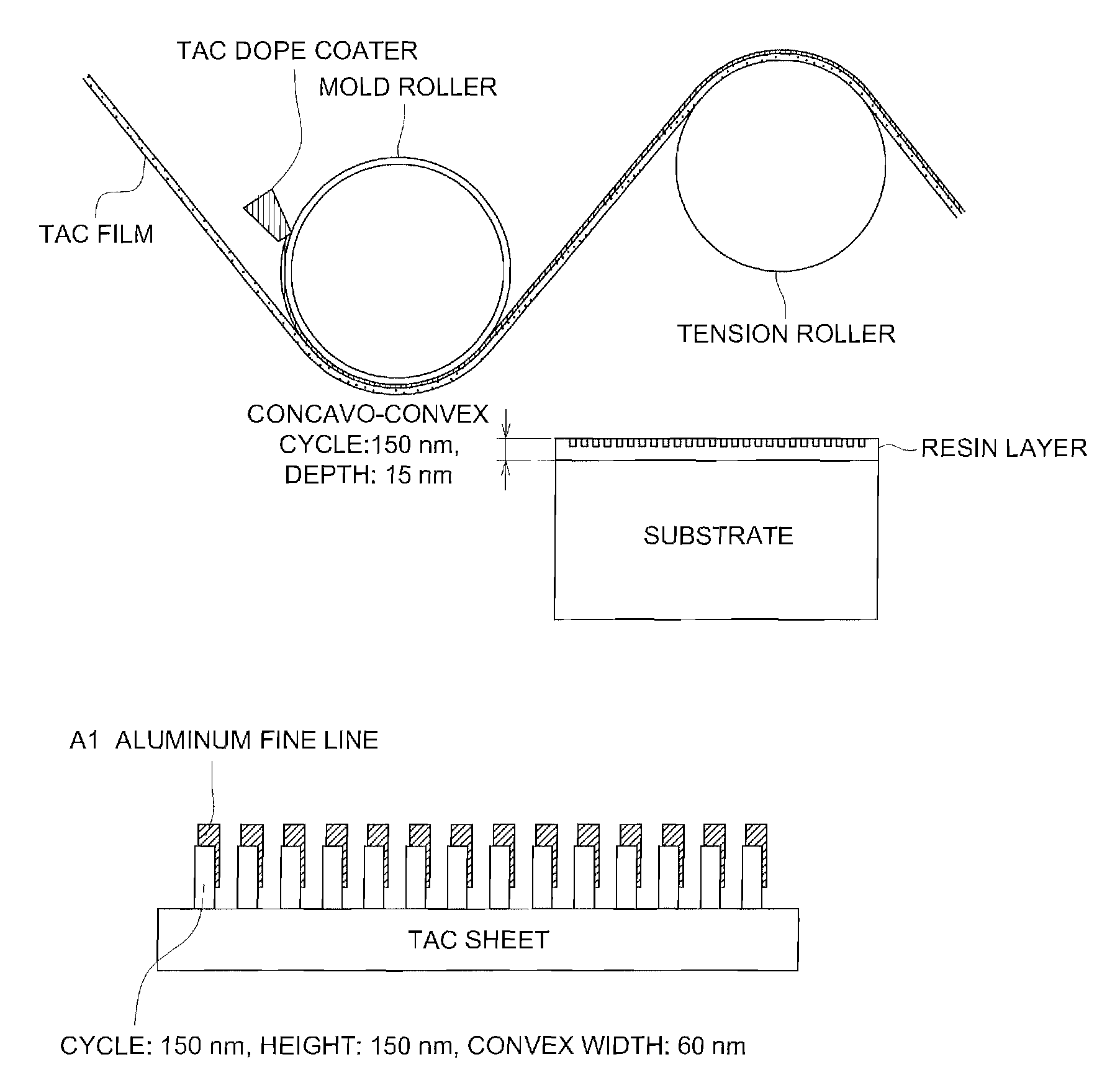
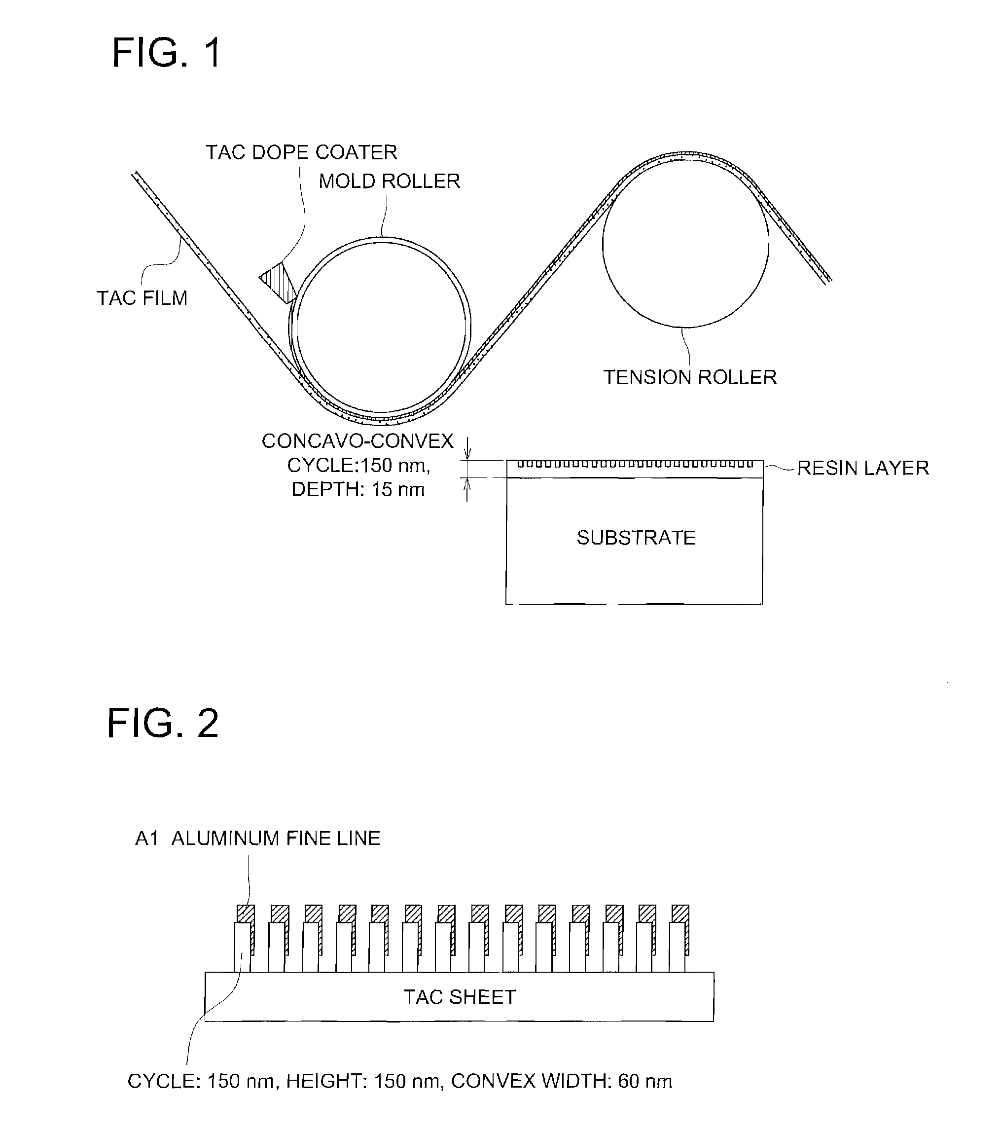
[1390]Metal fine lines of aluminum were formed at the concave portions of each of the cellulose ester films having the convexoconcave patters in the surface thereof prepared in Example 1.

[1391]The metal was put only on the concave portion of the film surface having the convexoconcave structure by vapor depositing the metal at a slanted direction. The thickness of the aluminum was 100 nm.

[1392]Thus prepared film on which the aluminum fine lines were formed had properties that the film permeated light polarized in the perpendicular direction to the fine lines and reflected light polarized in the direction of the fine lines. It could be confirmed that the luminance at the front surface of a liquid crystal display was raised by 1.4 times when the film was used as the luminance increasing film for the backlight of the liquid crystal display.

[1393]The cellulose ester films having the convexoconcave structure prepared in Example 1 were each subjected to the saponification treatment and use...


PUM

PropertyMeasurementUnit
Timeaaaaaaaaaa
Temperatureaaaaaaaaaa

Abstract

A manufacturing method of an optical film provided with a convexoconcave structure, comprises the steps of: coating a resin solution including a first resin solved by a solvent onto an endless or roll-like mold provided with a convexoconcave structure, and forming a resin solution layer on the mold; laminating a film substrate onto the resin solution layer to make a laminated film before the solvent in the resin solution layer is completely dried, the film substrate including a second resin, which is capable of absorving the solution or is soluble by the solvent; and peeling the laminated film from the mold before the solvent in the laminated film is completely dried.

Description

TECHNICAL FIELD[0001]The present invention relates to the method for manufacturing an optical film having a convexoconcave structure thereon, an optical film, a wire grid polarizer and a retardation film.RELATED ARTS[0002]In the field of display and others, there has been an intense demand for a large-area thin sheet provided with a convexoconcave structure. For example, a wire grid polarizer used to improve brightness and to separate polarized light can be manufactured by forming a metallic wire through the use of a convexoconcave structure. A convexoconcave structure having a pitch smaller than that of the wavelength can also be used in a retardation film based on the structural birefringence. It can also be used in an orientated film of a polarizer or liquid crystal and an antireflection structure.[0003]Nano-imprint technology is known as a method of manufacturing the thin sheet having a convexoconcave structure. A thermo-imprint technique has been proposed, wherein a heated mold...

Claims


Application Information

Patent Timeline
IPC IPC(8): G02B5/30B29D11/00G02B5/32
CPCB29C39/20B29D11/0073G02B5/3083C08J5/18G02B5/3058B29D11/00788B29D7/01B29C41/28G02B5/02
Inventor SATO, AKIRAIWAGAKI, MASARUSATO, HIROKAZUOHMORI, SHIGETOMIYAZAWA, KAZUHIROMURAKAMI, TAKASHIKOYAMA, HIROKAZUKUBO, NOBUOTASAKA, KOJIOKA, SHIGEKI
Owner KONICA MINOLTA OPTO
Why Eureka
Try Eureka