Scintillator single crystal and process for its production

a single crystal, scintillator technology, applied in the direction of crystal growth process, polycrystalline material growth, silicon compound, etc., can solve the problem of difficult to achieve stable light output properties, and achieve the effect of reducing the luminescent wavelength transmittance, increasing the variation of light output, and reducing the light outpu

Inactive Publication Date: 2007-12-20
HITACHI CHEM CO LTD
View PDF7 Cites 25 Cited by
  • Summary
  • Abstract
  • Description
  • Claims
  • Application Information

AI Technical Summary

Benefits of technology

[0031] However, it has been shown that the following phenomenon occurs with single crystals of the cerium-activated silicate compound represented by general formula (1) above and with single crystals of the cerium-activated gadolinium silicate compounds represented by general formulas (2) and (4) above, and especially with single crystals comprising as Ln at least one element selected from the group consisting of Dy, Ho, Er, Tm, Yb, Lu, Y and Sc which have smaller ion radii than Tb. Specifically, it has been demonstrated that growth or cooling of the single crystals in a low-oxygen neutral or reducing atmosphere or in a vacuum, or heat treatment in a low-oxygen neutral or reducing atmosphere or in a vacuum, leads to disadvantageous effects such as increased background light output and greater variation in light output. This phenomenon tends to be more pronounced with a lower oxygen concentration of the atmosphere, with a higher reducing gas (such as hydrogen) concentration of the atmosphere, and with a higher heating temperature.
[0032] One possible causative factor is that growth or heat treatment of such single crystals in a low-oxygen atmosphere produces oxygen defects in the crystal lattice. Presumably, the oxygen defects result in formation of an energy trap level, creating a background light output due to the effect of thermal excitation from that level and increasing variation in the light output.
[0033] The oxygen defects from the aforementioned cerium-activated orthosilicate compound single crystals tend to be fewer if the single crystals are grown in an oxygen-rich atmosphere. However, growth of single crystals in an oxygen-rich atmosphere promotes conversion of trivalent cerium ion (Ce3+) to tetravalent cerium ion (Ce4+), thereby lowering the luminescent wavelength transmittance and reducing the light output. Most of such orthosilicate single crystals have extremely high melting points of above 1600° C. The orthosilicate single crystals are grown by the Czochralski process which generally involves high-frequency heating in an Ir crucible, but exposing an Ir crucible to an oxygen-containing atmosphere at high temperatures of 1500° C. and above causes notable vaporization of Ir and tends to hinder crystal growth. Because of these two problems, cerium-activated orthosilicate single crystals are usually grown in low-oxygen neutral or reducing atmospheres, and consequently the issue of oxygen defects arises in the crystal growth stage.
[0034] Oxygen defects in cerium-activated orthosilicates tend to occur with crystal compositions that are inclined toward a C2 / c crystal structure. A P21 / c crystal structure will tend to be produced by using as Ln at least one element selected from the group consisting of La, Pr, Nd, Pm, Sm, Eu, Ga and Tb which have larger ion radii than Tb, for single crystals of the cerium-activated silicate compound represented by general formula (1) above and for single crystals of the cerium-activated gadolinium silicate compounds represented by general formulas (2) and (4) above. On the other hand, using as Ln at least one element selected from the group consisting of Dy, Ho, Er, Tm, Yb, Lu, Y and Sc which have smaller ion radii than Tb will tend to produce a C2 / c crystal structure. Such single crystals that tend to have a C2 / c crystal structure are more prone to increased background light output and variation in light output. This is believed to be because a larger difference between the ion radius of the activator Ce and the ion radius of the orthosilicate compound element results in more of the aforementioned oxygen defects.
[0035] In fact, in the case of single crystals of the cerium-activated gadolinium silicate compounds represented by general formula (2) above, the oxygen defects tend to be more abundant with a higher compositional ratio of Ln with small ion radii. With single crystals of cerium-activated orthosilicic acid compounds that are prone to oxygen defects due to the aforementioned crystal composition, it is believed that oxygen defects still occur even with heating in a neutral atmosphere or in a trace oxygen-containing neutral atmosphere or reducing atmosphere, or heating at a lower temperature.
[0036] Furthermore, it is thought that even Lu2-(1-x)Ce2-xSiO5 (cerium-activated lutetium orthosilicate) single crystals having a C2 / c crystal structure are prone to oxygen defects because of the large difference in ion radius compared to Ce ion.

Problems solved by technology

Consequently, the fluorescent properties tend to vary within crystal ingots and between crystal ingots, also varying from day to day and being altered when exposed to natural irradiation such as ultraviolet rays, and hence it has been difficult to achieve stable light output properties.

Method used


Image

  • Scintillator single crystal and process for its production
  • Scintillator single crystal and process for its production

Examples


example 1

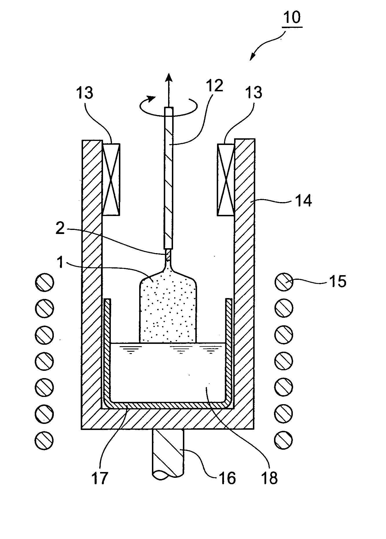
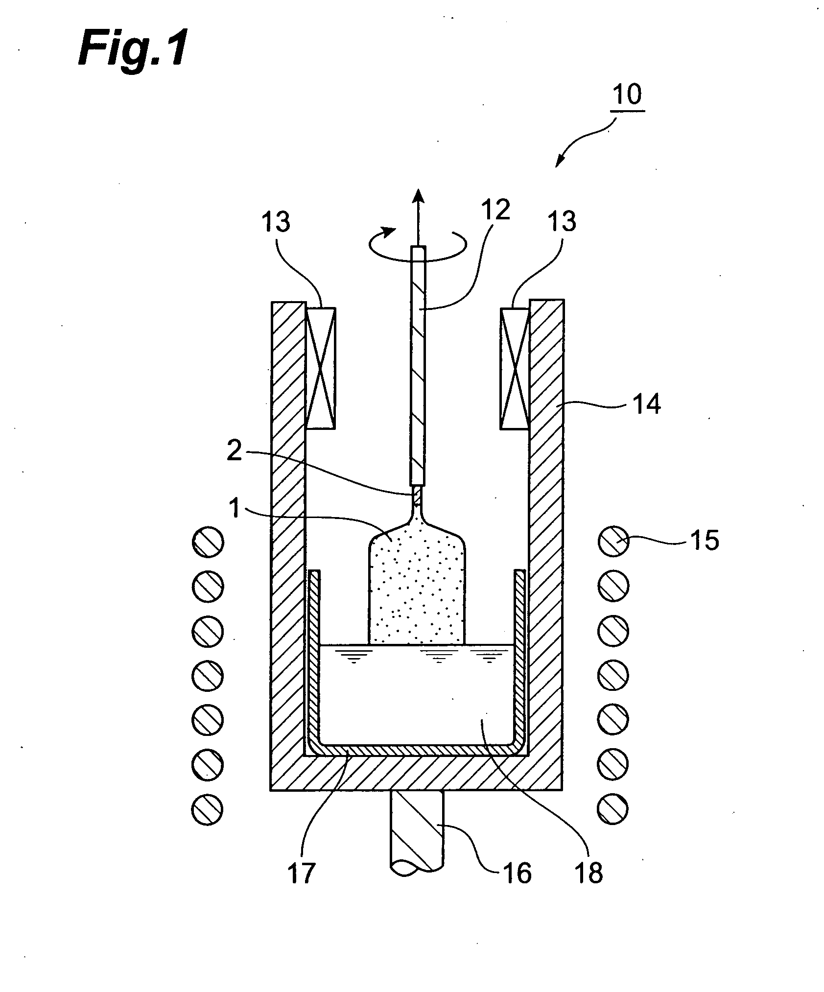
[0073] A single crystal was produced by the publicly known Czochralski process. First, 500 g of a mixture of gadolinium oxide (Gd2O3, purity: 99.99 wt %), lutetium oxide (Lu2O3, purity: 99.99 wt %), silicon dioxide (SiO2, purity: 99.9999 wt %) and cerium oxide (CeO2, purity: 99.99 wt %), in the prescribed stoichiometric composition, was prepared and loaded in an Ir crucible with a diameter of 50 mm, a height of 50 mm and a thickness of 2 mm, as the starting material for a Gd2-(r+s)LurCesSiO5 (r=1.8, s=0.003) single crystal. The tetra-, penta- and hexavalent elements (impurities) in the respective starting materials for gadolinium oxide, lutetium oxide and silicon dioxide were all less than 1 ppm by weight.

[0074] The mixture was then heated to the melting point (about 2050° C.) in a high-frequency induction heating furnace to obtain a melt. The melting point was measured using an electronic optical pyrometer (Pyrostar MODEL UR-U™ by Chino Corp.).

[0075] Next, the end of the lifting ...

example 2

[0079] First, 500 g of a mixture of gadolinium oxide (Gd2O3, purity: 99.99 wt %), lutetium oxide (Lu2O3, purity: 99.99 wt %), silicon dioxide (SiO2, purity: 99.9999 wt %) and cerium oxide (CeO2, purity: 99.99 wt %), in the prescribed stoichiometric composition as the starting materials for a Gd2-(r+s)LurCesSiO5 (r=1.8, s=0.003) single crystal, was loaded in an Ir crucible with a diameter of 50 mm, a height of 50 mm and a thickness of 2 mm, together with 0.0881 g of calcium carbonate (CaCO3, purity: 99.99 wt %) (corresponding to 0.0070 wt % as Ca). The tetra-, penta- and hexavalent elements (impurities) in the respective starting materials for gadolinium oxide, lutetium oxide and silicon dioxide were all less than 1 ppm by weight. The procedure thereafter was conducted in the same manner as Example 1.

example 3

[0080] A single crystal of Y2-(x+y)LuxCeySiO5 (x=1.8, y=0.003) instead of the Gd2-(r+s)LurCesSiO5 (r=1.8, s=0.003) in Example 1 was produced in the following manner. Yttrium oxide (Y2O3, purity: 99.99 wt %) was used instead of the gadolinium oxide (Gd2O3, purity: 99.99 wt %) used in Example 1, and into 500 g of a mixture with the prescribed stoichiometric composition there was loaded 0.0804 g of calcium carbonate (CaCO3, purity: 99.99 wt %) (corresponding to 0.0072 wt % of Ca) in the same manner as Example 2. The tetra-, penta- and hexavalent elements (impurities) in the respective starting materials for yttrium oxide, lutetium oxide and silicon dioxide were all less than 1 ppm by weight. The procedure thereafter was conducted in the same manner as Example 1.


PUM

PropertyMeasurementUnit
temperatureaaaaaaaaaa
melting pointaaaaaaaaaa

Abstract

The scintillator single crystal of the invention is a specific cerium-activated silicate single crystal wherein the total content of one or more elements selected from the group consisting of elements belonging to Groups 4, 5, 6 and Groups 14, 15, 16 of the Periodic Table is no greater than 0.002 wt % based on the total weight of the single crystal.

Description

BACKGROUND OF THE INVENTION [0001] 1. Field of the Invention [0002] The present invention relates to a scintillator single crystal and to a process for its production. More specifically, it relates to a scintillator single crystal used in a single-crystal scintillation detector (scintillator) for gamma ray or other radiation in the fields of radiology, physics, physiology, chemistry, mineralogy and oil exploration, such as for medical diagnostic positron CT (PET), cosmic radiation observation, underground resource exploration and the like, as well as to a process for its production. [0003] 2. Related Background Art [0004] Scintillators composed of cerium-activated gadolinium orthosilicate compounds have short fluorescent decay times and large radiation absorption coefficients, and are therefore employed as radiation detectors for positron CT and the like. The light output of such a scintillator is larger than that of a BGO scintillator, but is only about 20% of the light output of a...

Claims


Application Information

Patent Timeline
Patent Type & Authority Applications(United States)
IPC IPC(8): C01F17/00
CPCC01B33/20C30B29/34C30B15/00
Inventor KURATA, YASUSHISHIMURA, NAOAKIUSUI, TATSUYAKURASHIGE, KAZUHISA
Owner HITACHI CHEM CO LTD
Why Eureka
Try Eureka