Electrode for Hydrogen Generation, Method for Manufacturing the Same and Electrolysis Method Using the Same

Active Publication Date: 2008-02-07
TOSOH CORP
View PDF7 Cites 11 Cited by
  • Summary
  • Abstract
  • Description
  • Claims
  • Application Information

AI Technical Summary

Benefits of technology

[0053] In accordance with the present invention, an electrode for hydrogen generation can be easily obtained which has a low hydrogen overvoltage performance and excellent durability.
[0054] With regard to the electrode for hydrogen generation of the present invention, the hydrogen overvoltage does not rise as a result of poisoning due to iron ions in the electrolyte, which was a shortcoming of conventional platinum-type catalysts. Furthermore, peeling and exfoliation of the catalyst during elec

Problems solved by technology

However, in these electrodes, since it is necessary to make the supported material very thick, it is easy for distortions of the electrode and peeling of the supported material to occur as a result of the plating stress.
Also the activity of these base metals are low.
Therefore, the improvement of the activity by alloying the base metals alone was insufficient as an effect that decreases the hydrogen overvoltage.
Furthermore, an electrode in which an alloy layer containing nickel and molybdenum is supported by the arc ion plating method has been disclosed (Patent Document 3); however, despite the initial hydrogen overvoltage being sufficiently low, there was a problem in the hydrogen overvoltage rising during long electrolysis operations, or the so-called durability.
Therefore, there were problems such as the production costs being very high.
When this value is converted to a hydrogen overvoltage, it is approximately 120 mV, and the hydrogen overvoltage performance is insufficient.
That is to say, each of the electrodes for hydrogen generation proposed in Patent Document 5 which are achieved by coating various metals or the oxides thereof such as a platinum group metal together with Ni or a Ni alloy were not satisfactory in the overvoltage performance.
Therefore, there was a problem that should be improved.
However, with regard to these electrodes for hydrogen generation, it is known that they possess a problem in that they are susceptible to poisoning as a result of impurities such as iron in the electrolyte (Patent Document 8 and Patent D

Method used


Image

  • Electrode for Hydrogen Generation, Method for Manufacturing the Same and Electrolysis Method Using the Same
  • Electrode for Hydrogen Generation, Method for Manufacturing the Same and Electrolysis Method Using the Same
  • Electrode for Hydrogen Generation, Method for Manufacturing the Same and Electrolysis Method Using the Same

Examples


example 1

[0162] A nickel expanded mesh (10×10 cm) was used as the conductive base material, and as a roughening process, etching was performed using a 10 wt % hydrochloric acid solution at a temperature of 50° C. for 15 minutes, and then water washing and drying were performed.

[0163] Next, the coating solution (mixed solution) in which a platinum content was 0.5 by mole ratio and a total concentration of platinum and nickel was 5 wt % by metal conversion was prepared using a dinitrodiammine platinum nitrate solution (manufactured by Tanaka Noble Metals Ltd., platinum concentration: 4.5 wt %, solvent: 8 wt % nitric acid solution), nickel nitrate hexahydrate, and water.

[0164] Next, this coating solution was coated on all over the surface of the nickel expanded mesh using a brush, and was dried at 80° C. for 15 minutes in a hot air type dryer, and then thermal decomposition was performed under a circulation of air at 500° C. for 15 minutes using a box-shaped muffle furnace (manufactured by Ad...

examples 2 to 8

[0172] Except using cobalt nitrate hexahydrate as the additional metal compound and changing the platinum and cobalt contents in the coating solution, the electrodes for hydrogen generation were prepared and evaluated by the same operations as Example 1.

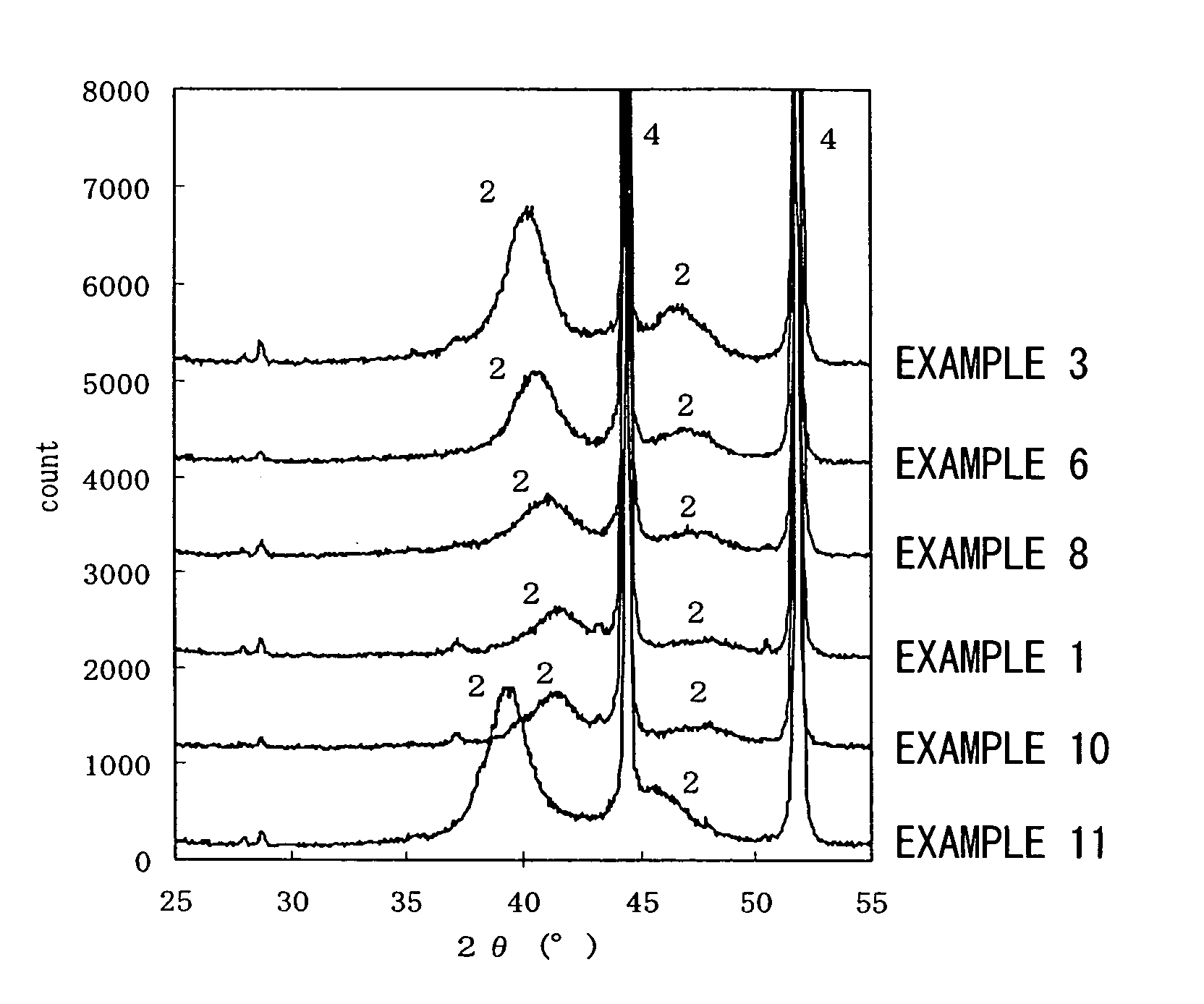
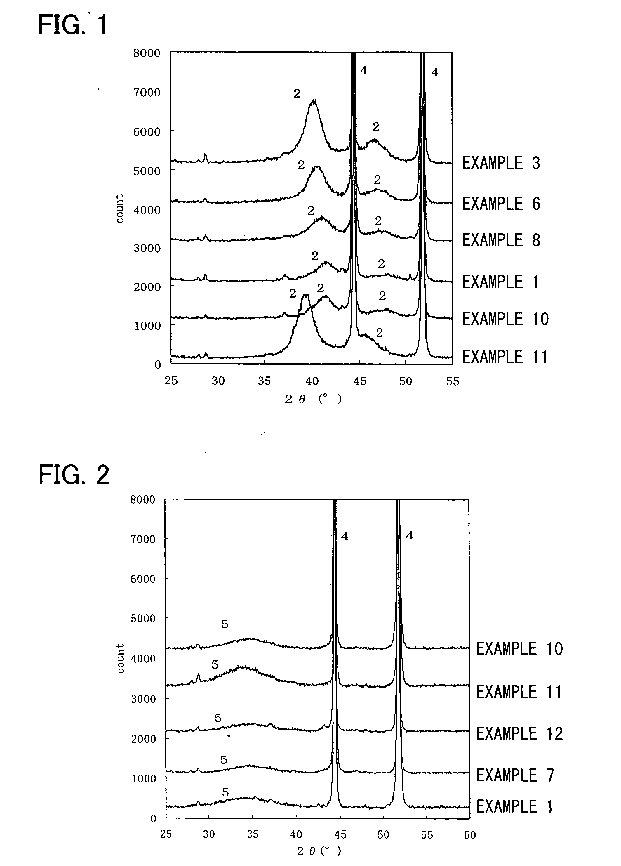
[0173] The results evaluated by the above-mentioned methods are shown in Tables 1 and 2, and the X-ray diffraction diagrams of Examples 3, 6, and 8 after the reduction process are shown in FIG. 1. Furthermore, the X-ray diffraction diagram of Example 7 after the thermal decomposition process and before the reduction process is shown in FIG. 2.

[0174] From FIG. 2, with regard to Example 7, nickel peaks (4) of the base material and a broad peak (5) of the amorphous material including cobalt which is the additional metal and platinum were recognized in the X-ray diffraction diagram before the reduction process.

examples 9 to 10

[0175] Except using copper nitrate trihydrate as the additional metal compound and changing the platinum and copper contents of the coating solution, thermal decomposition was performed by the same operations as Example 1. The reduction process was performed by immersing in 100 mL of a hydrazine aqueous solution with a concentration of 5 wt % at room temperature overnight and then the electrode was washed by water and dried; thereby, the electrodes for hydrogen generation were prepared.

[0176] The electrodes were evaluated by the above-mentioned methods. The results thereof are shown in Tables 1 and 2, and the X-ray diffraction diagram of Example 10 after the reduction process is shown in FIG. 1. Furthermore, with regard to Example 10, the X-ray diffraction diagram after the thermal decomposition process and before the reduction process is shown in FIG. 2.

[0177] From FIG. 2, with regard to Example 10, nickel peaks (4) of the base material and a broad peak (5) of the amorphous mater...


PUM

PropertyMeasurementUnit
Temperatureaaaaaaaaaa
Timeaaaaaaaaaa

Abstract

The present invention provides an electrode for hydrogen generation of which the hydrogen overvoltage is sufficiently low and which is not affected by poisoning due to iron ions, and furthermore, of which the durability is superior because during operations and stop-and-start control, the hydrogen overvoltage does not rise and exfoliation of the supported material does not occur. The present invention also provides a method for manufacturing the aforementioned hydrogen generation electrode and an electrolysis method using the electrode for hydrogen generation as a cathode. An electrode for hydrogen generation is used in which a platinum alloy including platinum and one metal selected from the group consisting of nickel, cobalt, copper, silver, and iron, or an amorphous material of a transition metal element and platinum is supported on a conductive base material. This electrode is obtained by coating a metal compound solution including one selected from the group consisting of nickel, cobalt, copper, silver, and iron, and a platinum compound solution which forms an ammine complex; drying; thermally decomposing at a temperature in a range from more than 200° C. to 700° C. or less; and then subjecting to a reduction processing.

Description

TECHNICAL FIELD [0001] The present invention relates to an electrode for hydrogen generation that is utilized in the electrolysis of water, or in the electrolysis of alkali metal chloride aqueous solutions such as sodium chloride, a method for manufacturing the same, and an electrolysis method using the same. BACKGROUND ART [0002] Industries of water electrolysis or alkali metal chloride aqueous solution electrolysis are heavy power-consuming type industries, and a variety of technology developments are being performed for energy saving. The method for saving energy thereof involves substantially reducing the electrolysis voltage which includes the theoretical decomposition voltage, the solution resistance, the ion-exchange membrane resistance, the anode overvoltage, the cathode overvoltage, and the like. [0003] In particular, in relation to reducing the overvoltage, since the overvoltage value thereof is influenced by the catalyst material of the electrode, the morphology of the el...

Claims


Application Information

Patent Timeline
IPC IPC(8): C02F1/461C01B3/00C01B7/07C02F1/40C25B1/04C25B1/16C25B11/04C25B11/08
CPCC25B11/0478Y02E60/324Y02E60/366C25B11/0494Y02E60/36C25B11/097C25B11/091Y02E60/32
Inventor SHIRAKURA, YOSHINORISHIMONO, AKINORI
Owner TOSOH CORP
Why Eureka
Try Eureka