Polymeric coatings and methods for forming them

a polymer coating and surface technology, applied in the direction of coatings, liquid surface applicators, pretreated surfaces, etc., can solve the problems of affecting provoking an undesired biological response, etc., to achieve the effect of improving the stability and insolubility of the macromolecular coating, reducing the risk of gastrointestinal

Inactive Publication Date: 2008-02-21
COMMONWEALTH SCI & IND RES ORG
View PDF5 Cites 65 Cited by
  • Summary
  • Abstract
  • Description
  • Claims
  • Application Information

AI Technical Summary

Benefits of technology

[0015] Advantageously, the present invention relates to a method of forming a polymeric surface coating which reliably achieves predetermined surface coating characteristics, such as density, evenness and thickness. This advantage is achieved at a first level by control over the density and distribution of polymerisation initiators on a macromolecule covalently bound to the surface of a substrate and at a second level by control over the formation of pendant polymers by grafting from the polymerisation initiators.
[0130] Example 19 demonstrates the stability of coatings made in accordance with the present invention.

Problems solved by technology

However, in many applications the surface properties of the substrate material are not suitable or ideal for the intended application.
However, the surface properties of the bulk material may interfere with a desired biological response, such as cell attachment, or may provoke an undesired biological response, such as protein fouling.
However, adsorbed coatings may desorb under certain conditions, which limits the appropriateness of adsorption as a surface modification technique in a variety of biomedical applications.
For example, devices designed to remain in physiological conditions for an extended period of time, such as implants, may lose their functional surface coating, leaching polymers into their environment.
Furthermore, simple adsorption is not readily applicable to a large variety of substrate materials, as the properties of the substrate are not suitable for attracting and retaining the coating polymers.
Disadvantages of this approach include the possibility of desorption of the coating as described for the adsorbed surface modification techniques.
Furthermore, control over the grafted polymer coating architecture is limited.
This approach typically leads to an indeterminate and inconsistent density of the initiator across the surface of a substrate, which is often undesirable.
Furthermore, disadvantageously the initiator density that can be achieved with this procedure is limited.
Finally, there is only limited control over the subsequently grafted coating architecture.
Disadvantages of this approach again include an indeterminate, inconsistent, and limited density of the initiator across the surface of a substrate and limited control over the grafted coating architecture.
Furthermore, this approach uses a multi-step surface coating approach which limits its applicability and usefulness to silica-type materials.
Again, this technique uses a multi-step surface coating approach which limits its applicability.
Other disadvantages of this approach again include an indeterminate, inconsistent and limited density of the initiator across the surface of a substrate and limited control over the grafted coating architecture.
Apart from substrate dependency issues, disadvantages of this approach again include the indeterminate, inconsistent and limited density of the initiator across the surface of a substrate and limited control over the grafted coating architecture.
Furthermore, the lack of covalent attachment can lead to partial desorption of the coating.
However, reliance on the use of substrates such as silica and gold limits the applicability of this technology.
In addition, further disadvantages include, that self assembled layers formed from silanes have been shown to be somewhat unstable [Wang, A. et al., Journal of Colloid and Interface Science, 291 (2005) 438] and irreproducible [Halliwell, C. M., Cass, A. E. G., Analytical Chemistry 73 (2001) 2476] and that self assembled layers formed between gold and thiols (a non-covalent interaction) have been shown to be unstable with time [Willey, T. M. et al., Surface Science 576 (2005) 188].
Furthermore, the formation of such modified surfaces is relatively complex (with the requirement that the substrate be scrupulously clean and dry) and the surface coating may not be evenly distributed on the substrate.
However, as previously discussed, surface modification schemes designed for particular substrates, such as silica and polystyrene, severely limits the applicability of the technology.

Method used


Image

  • Polymeric coatings and methods for forming them
  • Polymeric coatings and methods for forming them
  • Polymeric coatings and methods for forming them

Examples


example 1

Deposition of an n-Heptylamine Radio Frequency Glow Discharge (RFGD) Thin Film on Silicon Wafer Substrates

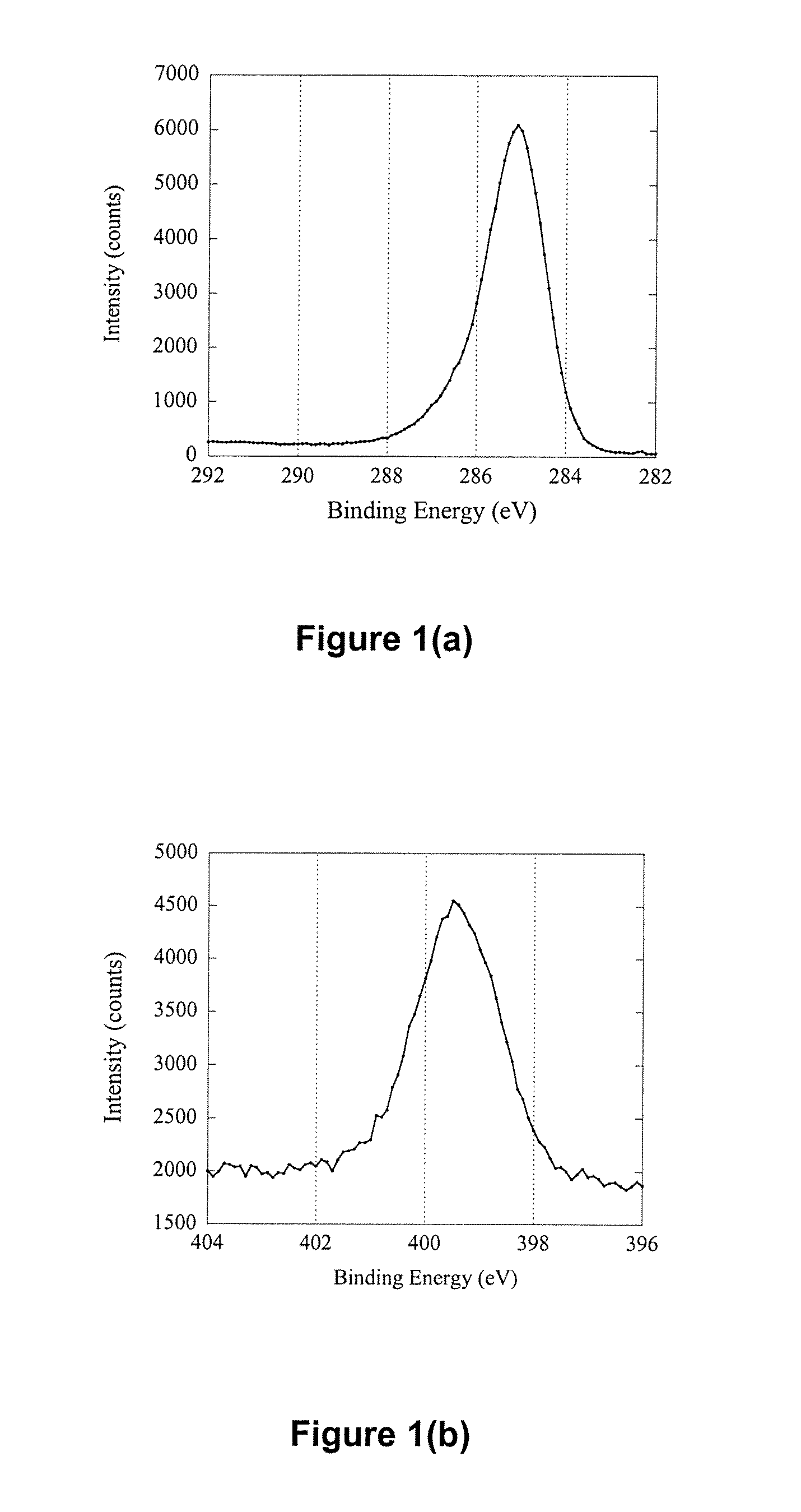
[0176] Silicon wafers (Si) with a size of 1 cm×1 cm were cleaned by sonication in a 2% RBS surfactant solution for 30 min followed by thorough rinsing in Milli-Q™ water and ethanol. After drying with a high velocity, purified N2 stream, the wafers were introduced immediately into a radio frequency glow discharge plasma reactor described elsewhere [Griesser H J., Vacuum 39 (1989) 485]. Deposition of an n-heptylamine plasma polymer (HAPP) thin film was carried out for 30 s at a power of 20 W, a frequency of 200 KHz and an initial monomer pressure of 0.150 Torr. Presented in Table 1 are elemental ratio data before and after HAPP thin film deposition. The elemental ratios were calculated from the surface composition of the two samples obtained using X-ray Photoelectron Spectroscopy (XPS). The first point of interest was that the Si / C ratio was decreased from 12.10 to 0.00 after sur...

example 2

Synthesis of Diethyl-Dithiocarbamic Acid 4-Vinyl-Phenyl Ester

[0177] A solution of sodium diethyldithiocarbamate trihydrate (3.5 g, 1.55×10⁻² mol) in 20 mL of ethanol was added to a flask equipped with a stirrer, dropping funnel and a reflux condenser. To this solution was added a solution of 4-vinylbenzyl chloride (3.0 g, 1.96×10⁻² mol) and ethanol (5 mL), dropwise, over a period of 0.5 h at a temperature of 0° C. The resultant solution was stirred at room temperature for 24 h before pouring into a large volume of water and extracting with diethyl ether. The ether phase was washed three times with water, dried over sodium sulphate, before finally removing the diethyl ether by evaporation. The residue was recrystallised three times from methanol, giving a yield of 2.6 grams (83%). 1H NMR (CDCl3) δ7.36 (s, 4H, C6H4), 6.70 (dd, J=11.6 and 17.5 Hz, 1H, CH═CH2), 5.73 (d, J=17.5 Hz, 1H, CH═CH2), 5.24 (d, J=11.5 Hz, 1H, CH═CH2), 4.54 (s, 2H, CH2S), 4.04 (q, J=7.3 Hz, 2H, NCH2), 3.73 (q, J...

example 3

Synthesis of a Polymer Containing Carboxylic Acid Moieties and Iniferter Moieties

[0178] Acrylic acid (3.0 g, 4.16×10⁻² mol, anhydrous, Fluka) was dissolved in 6 mL of dimethylformamide (DMF) (BDH chemicals), followed by removal of the inhibitor by passage of the solution through a column containing Inhibitor Remover (Aldrich). To the acrylic acid solution was added 1.1 g of diethyl-dithiocarbamic acid 4-vinyl-phenyl ester (4.38×10⁻³ mol) (from Example 2) and 150 mg of AIBN, following which the solution was purged with nitrogen for 10 min and sealed. Heating overnight at 60° C. resulted in the formation of an opaque, viscous gel which was diluted by further addition of 20 mL of DMF. The solution containing the copolymer was then dialysed (Spectrum Spectra / Por 1 molecular porous membrane tubing, MW cutoff 6000-8000) against DMF overnight. The DMF was changed twice during dialysis. The contents of the dialysis tube were then transferred to a flask and made up to a final volume of 50 m...


PUM

PropertyMeasurementUnit
thicknessaaaaaaaaaa
thicknessesaaaaaaaaaa

Abstract

The present invention relates to a controllable polymeric surface coating including a macromolecule, which is covalently bound to the surface of a substrate, the macromolecule including a plurality of polymerisation initiators and a plurality of surface binding groups; and pendant polymers grafted from at least some of the polymerisation initiators.

Description

FIELD OF THE INVENTION [0001] The present invention relates to methods and processes for modifying the surface of a variety of substrate materials (including organic and inorganic substrates). More particularly, the present invention relates to at least partially coating the surface of a substrate with polymers so as to impart a functional property to the surface of the substrate, which is distinct from the functional properties of the remainder of the substrate. For example, in biomedical applications the functional property imparted to the surface of a substrate may be the ability to induce a particular biological response. BACKGROUND OF THE INVENTION [0002] In many applications it is important to differentiate between the bulk properties of a material or device and the surface properties of that material or device. The bulk or substrate material provides a set of bulk properties suitable for the intended application, such as mechanical properties or refractive properties. However...

Claims


Application Information

Patent Timeline
Patent Type & Authority Applications(United States)
IPC IPC(8): C08F120/18
CPCC08J7/123
Inventor MEAGHER, LAURENCETHISSEN, HELMUTPASIC, PAULEVANS, RICHARD ALEXANDERJOHNSON, GRAHAM
Owner COMMONWEALTH SCI & IND RES ORG
Why Eureka
Try Eureka