
Functional particle and manufacturing method thereof

a technology of functional particles and manufacturing methods, applied in the field of functional particles, can solve the problems of image defects, inability to form high-quality images, unevenness in images, etc., and achieve the effects of no fluctuation, excellent retainability or storage, and high fineness

Active Publication Date: 2008-03-13
SHARP KK
View PDF18 Cites 32 Cited by
  • Summary
  • Abstract
  • Description
  • Claims
  • Application Information

AI Technical Summary

Benefits of technology

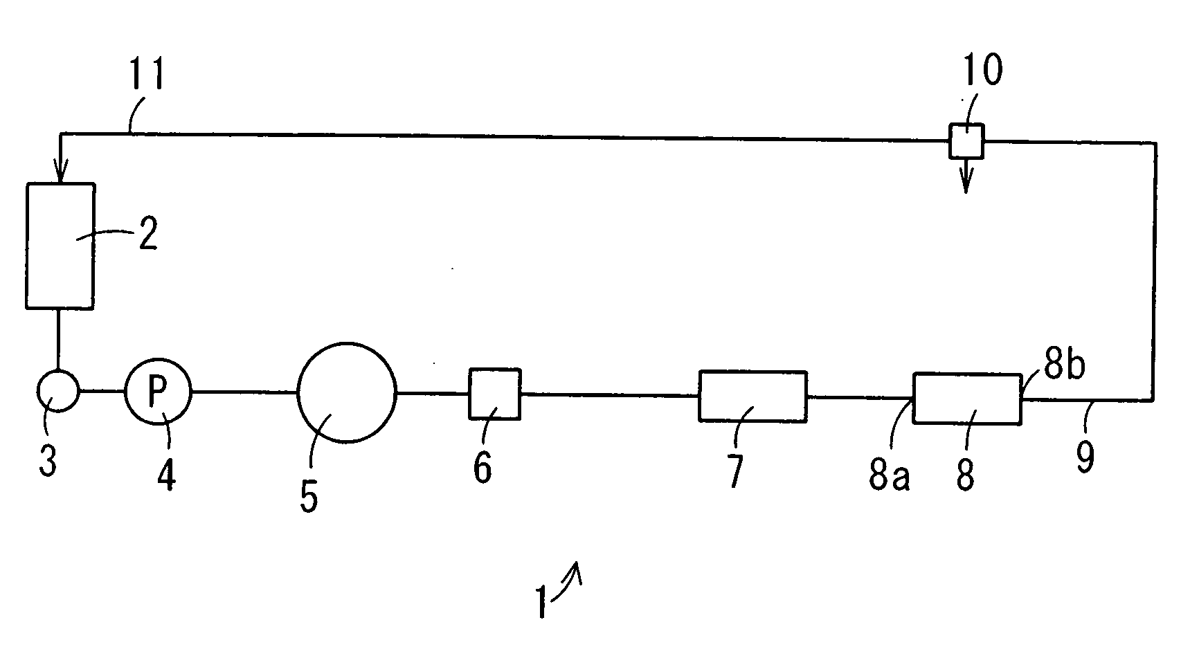
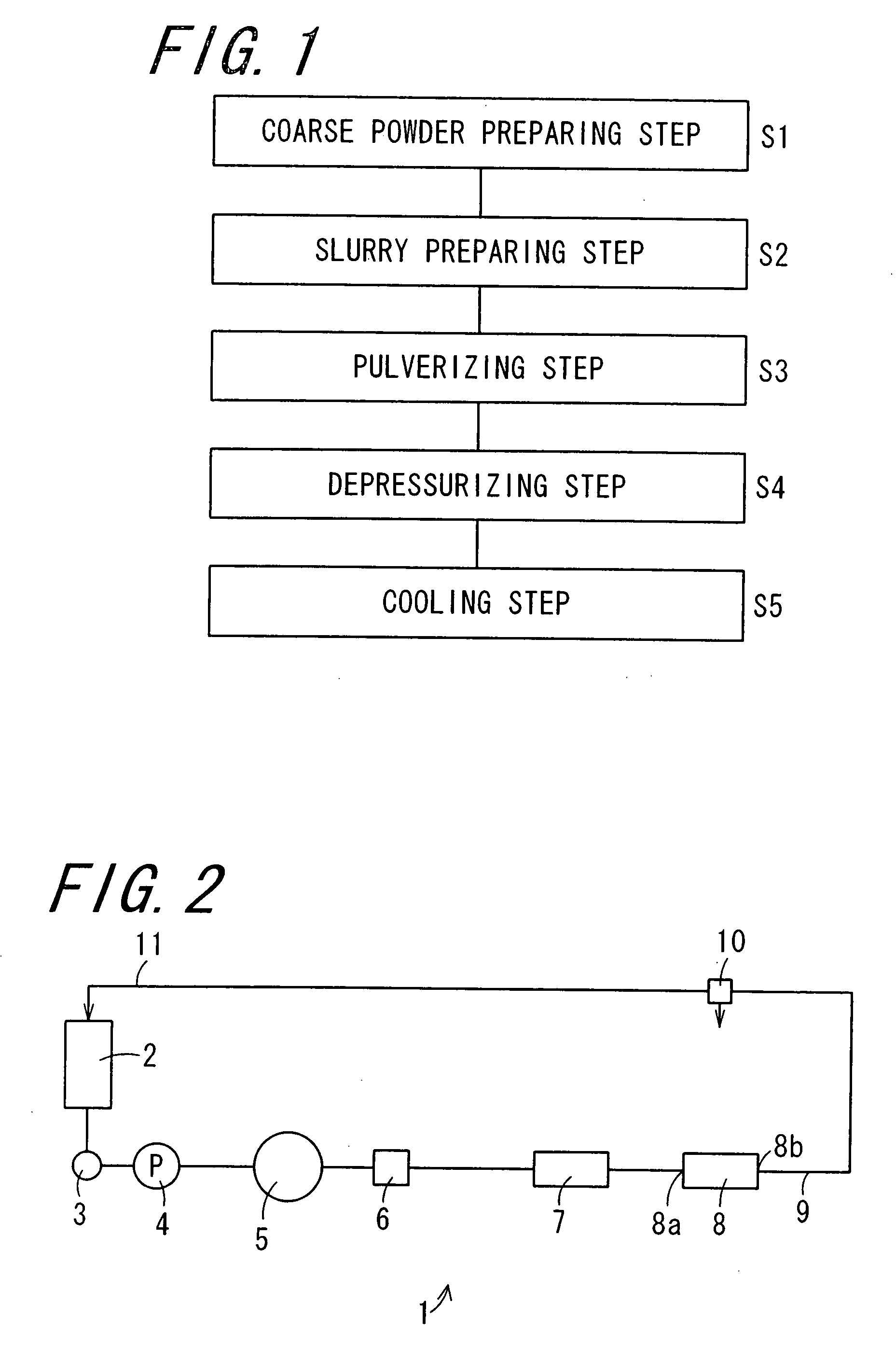
The invention provides a manufacturing method for a functional particle with a uniform shape, size, and property distribution. The method involves depositing a shell particle of a smaller grain size onto a core particle through a coiled pipeline while heating the mixed slurry containing the particles. The resulting functional particle has a coating layer that is uniform in shape and size, with a narrow range of grain size distribution and low fluctuation in properties. The method is simple and scalable, and can produce a high yield of functional particles. Additionally, the method includes steps of depressurizing and cooling the slurry to prevent coagulation between the particles and improve the yield of functional particles. The functional particle has a uniform shape and property distribution, and is suitable for various industrial applications.

Problems solved by technology

As a result, image defects such as unevenness in images tends to occur and images at high quality cannot be formed.
It is extremely difficult to control the surface state of the toner in the reduction of the particle size by pulverization.
Further, the release agent contained in the toner has a property of bleeding out to the toner surface with time.
Since the release agent has tackiness, it tends to cause aggregation (blocking) between the toners.
In a case of using a two-component developer containing a toner and a carrier, a phenomenon referred to as filming in which the release agent in deposited to the carrier surface occurs, which deteriorates the carrier and makes charging of the toner insufficient.
However, since the binder resin tends to be softened by heat, the toner tends to cause blocking.
In a case of using this toner, since the range for the possible fixing temperature is narrowed, it requires to conduct temperature control accurately during fixing which renders the control complicated during fixing.
However, the spray drying method inevitably forms coarse coagulates and increases the width of the grain size distribution to vary the charging performance of the toner.
Further, by the manufacturing method of JP-A 4-174861, a great amount of vapors of methylethyl ketone as an organic solvent is formed, which cannot be exhausted as it is in atmospheric air.
Therefore, it needs a special recovery facility and is not suitable to production in an industrial scale.
However, since the mechanical impact force or dry mechanochemical method has to be applied in an air stream at low particle concentration and the production efficiency is low, it is not suitable to the production in an industrial scale.
The manufacturing method involves a problem that aggregation of the colorant tends to occur upon mixing the toner raw material mixture and the aqueous medium due to the less dispersibility of the colorant to water.
Further, aggregation of the colorant varies the colorant content in the finally obtained encapsulated toner to make the charging performance not uniform.
Accordingly, aggregation occurs between the primary particles to each other or between secondary particles to each other and the aimed encapsulated particles cannot be obtained by a yield at an industrially satisfactory level.
In addition, the grain size of the obtained encapsulated particles is not uniform and the width of the grain size distribution is broad.
Further, in the technique of JP-A 63-278547, since aggregation is conducted at a high pressure of 29.4 MPa or higher and at 54.8 MPa or higher depending on the case, a pressure proof facility and an arresting facility are indispensable for the practice of an industrial scale and increase in the size of the homogenizer is also required, so that this is not a practical method.
Further, since only the secondary particles having a volumic average grain size ⅕ or less of the volumic average particle size of the primary particle can be used, usable secondary particles are restricted.

Method used


Image

  • Functional particle and manufacturing method thereof
  • Functional particle and manufacturing method thereof
  • Functional particle and manufacturing method thereof

Examples


production example 1

[0124][Preparation of Coarse Powder Slurry]

[0125]100 parts of a polyester resin (glass transition temperature Tg: 60° C., softening temperature Tm: 110° C.) were melted and kneaded by a twin screw extruder (PCM-30, trade name of products manufactured by Ikegai Ltd.) at a cylinder temperature of 145° C. and a number of rotation of a barrel of 300 rpm to prepare a molten kneaded mixture for a toner material. After cooling the molten kneaded product to a room temperature, it. was coarsely pulverized by a cutter mill (VM-16; trade name of products manufactured by SEISHIN ENTERPRISING CO., LTD.), to prepare a coarse powder with a grain size of 100 μm or less. 40 g of the coarse powder, 13.3 g of xanthan gum, 4 g of sodium dodecyl benzene sulfonate (LUNOX S-100, trade name of products for anionic dispersant manufactured by Toho Chemical Industry Co., Ltd.), 0.67 g of sulfosuccinic acid surfactant (trade name: Airol CT-1P, main ingredient: sodium dioctyl sulfosuccinate salt manufactured by...

production example 2

[0128][Preparation of Core Particles]

[0129]An aqueous slurry containing core particles with a volume average grain size of 4.4 μm, a CV value of 23%, a glass transition temperature of 53° C., and a melting point of 110° C. was prepared in the same manner as the Production Example 2 except for using, instead of 100 parts of the polyester resin, 100 parts of a mixture obtained by mixing 87.5 parts of a polyester resin, 1.5 parts of a charge controller (TRH, trade name of products manufactured by Hodogaya Chemical Co. Ltd.), 3 parts of a polyester wax (melting point: 85° C.), and 8 parts of a colorant (KET. BLUE 111) by a mixer (Henschel mixer, trade name of products manufactured by Mitsui Mining Co).

production example 3

[0130][Preparation of Shell Particles]

[0131]An anchor type stirring blade was attached to a separable flask, and 0.1 parts of ammonium dodecyl sulfonate (emulsifier) dissolved in 390 parts of ion exchanged water was charged and heated to a temperature of 80° C. The temperature was kept at 80° C. and an aqueous solution comprising one part of 2,2′-azobis-2-amidinopropane dihydrochloride (polymerization initiator, V-50, trade name of products manufactured by Wako Pure Chemical Industries Ltd.), and 10 parts of ion exchanged water, and a mixture comprising monomers for polymerization (10 parts of styrene monomer, 40 parts of methyl methacrylate, and 15 parts of n-butyl methacrylate) and one part of octyl thioglycolate (chain transfer agent) were dropped respectively for 60 min. After 30 min from the completion of dropping, a mixed monomer comprising 10 parts of styrene, 15 parts of methyl methacrylate, and 5 parts of n-butyl methacrylate was dropped for 30 min. After completion of the ...


PUM

PropertyMeasurementUnit
volume average grain sizeaaaaaaaaaa
number average particle sizeaaaaaaaaaa

Abstract

A functional particle is manufactured by a method including an aggregating step, a depressurizing step, and a cooling step. In the aggregating step, the functional particle is obtained by flowing a mixed slurry containing a core particle and a shell particle through a coiled pipeline while heating the mixed slurry to a glass transition temperature or higher of the core particle, to deposit the shell particles on the surface of the core particle. In the depressurizing step, the grain size of the functional particle is controlled and the coarse particle is pulverized to make the grain size of the functional particles uniform. In the cooling step, re-aggregation of the functional particles with unified grain size is prevented.

Description

CROSS-REFERENCE TO RELATED APPLICATION[0001]This application claims priority to Japanese Patent Application No. 2006-244724, which was filed on Sep. 8, 2006, the contents of which are incorporated herein by reference in its entirety.BACKGROUND OF THE INVENTION[0002]1. Field of the Invention[0003]The present invention relates to a functional particle and a method of manufacturing the same.[0004]2. Description of the Related Art[0005]A toner used for elecrophotographic image formation contains a binder resin, a colorant, a release agent and the like. A typical method of manufacturing the toner includes a pulverization method. According to the pulverization method, a toner of an infinite form is manufactured by cooling to solidify a molten kneaded product of a binder resin, a colorant, a wax and the like and mechanically pulverizing the obtained solidification product. In the toner, since a fractured surface during pulverization appears on the surface, the colorant is often exposed to ...

Claims


Application Information

Patent Timeline
Patent Type & Authority Applications(United States)
IPC IPC(8): G03G9/093
CPCG03G9/09307G03G9/09314G03G9/09392G03G9/09357G03G9/09371G03G9/09321
Inventor KIKAWA, KEIICHIMATSUMOTO, KATSURUMAEZAWA, NOBUHIRO
Owner SHARP KK
Learn More