
Light-Emitting Electrochemical Cell

a technology of electrochemical cells and light-emitting electrodes, which is applied in the direction of electrochemical generators, natural mineral layered products, transportation and packaging, etc., can solve the problems of easy oxidation, shortening the life, and pled/oled devices for large-area lighting, and achieves high brightness and high efficiency.

Inactive Publication Date: 2008-04-24
KONINKLIJKE PHILIPS ELECTRONICS NV
View PDF3 Cites 10 Cited by
  • Summary
  • Abstract
  • Description
  • Claims
  • Application Information

AI Technical Summary

Benefits of technology

[0011]An object of the present invention is to provide LEECs having high efficiencies at high brightness levels.
[0016]The electroluminescent material may further comprise a substance selected from the group consisting of polyacrylates, polymethacrylates, polyethers, polyesters, polyolefines, polystyrenes, polysiloxanes or mixtures or mixtures or derivatives thereof. For example, the electroluminescent material may comprise polymethylmetacrylate (PMMA). Thereby, film formation is improved resulting in less leakage current and therefore higher efficiency.
[0017]The electrode of the LEEC may comprise a material selected from the group consisting of Au, Ag, Al, Pt, Cu, Zn, Ni, Fe, Pb, In, W, Pd, indium tin oxide (ITO), indium zinc oxide, lead oxide, tin oxide, graphite, doped silicon, doped germanium, doped gallium arsenide, doped polyalinine, doped polypyrrole, doped polythiophene, and derivatives and mixtures thereof. These materials are non-reactive and therefore very advantageous to use as electrodes.

Problems solved by technology

However, the main disadvantages of using PLED / OLED devices for large-area lighting are:
These metals are very easily oxidized, which shortens the lifetime and requires special packaging of the device. the electroactive layer has to be thin (˜70 nm) because the current, and thus the light output, decreases dramatically with increasing thickness.
The processing of large-area layers of such thickness, avoiding shorts and light inhomogeneities, is very difficult.
One of the main problems for LEEC is that the performance in terms of efficiency has not yet reached the level of existing light sources or competing technologies for solid-state lighting (i.e. inorganic and organic LEDs).
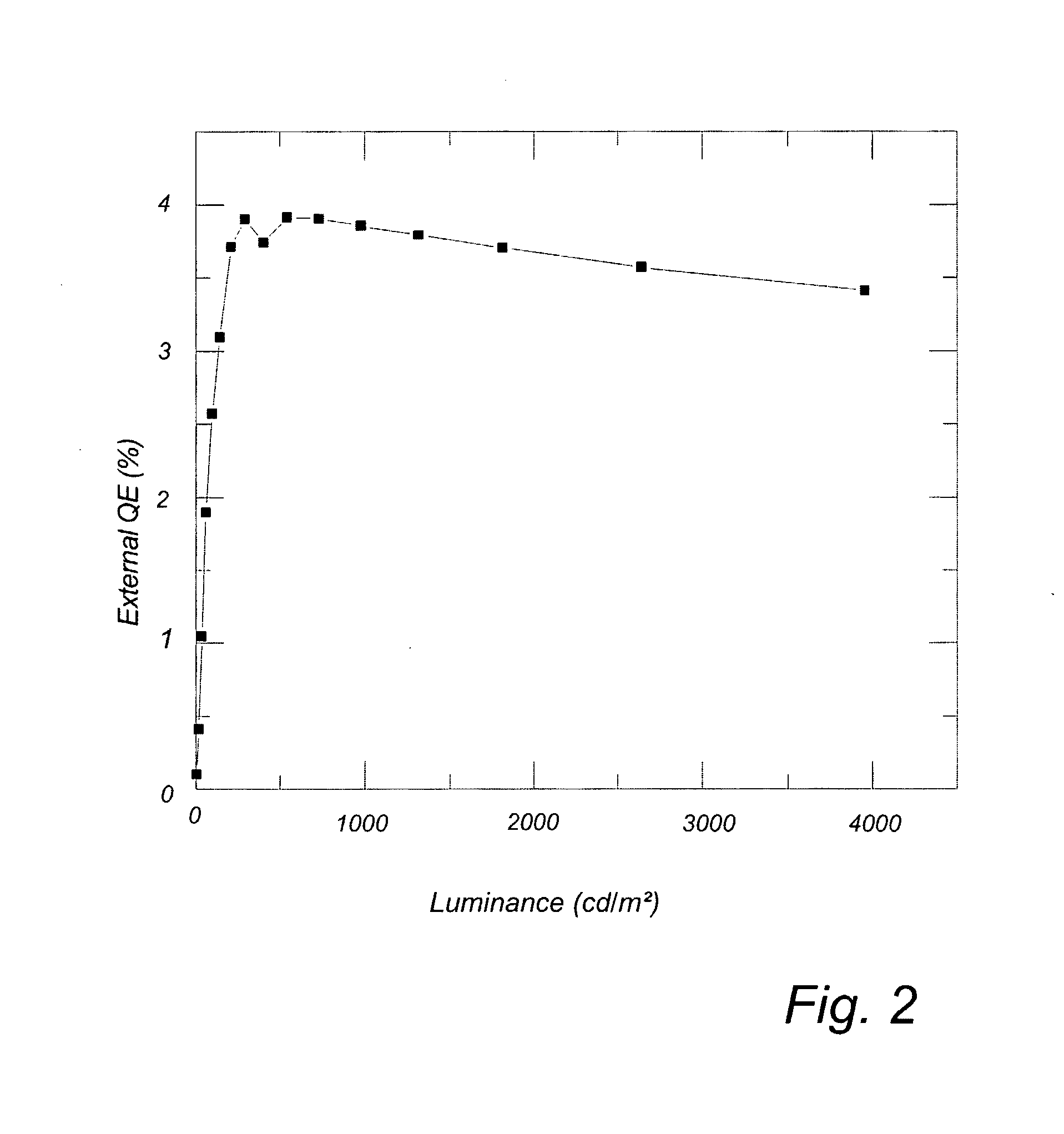
However, the corresponding luminance was only up to 330 cd / m2, which is too low for lighting applications.
Higher luminance levels could be obtained by applying a higher voltage (−5V) or by using a low-work function electrode (Ca), but in both cases the efficiency was not high over a reasonable luminance range, and also not stable.
All prior art LEECs thus suffer from the drawback of deteriorated brightness at higher efficiency levels.

Method used


Image

  • Light-Emitting Electrochemical Cell
  • Light-Emitting Electrochemical Cell
  • Light-Emitting Electrochemical Cell

Examples


example 1

Synthesis of [Ir(ppy)2(phen)]+(PF6−)

[0064]Ir2Cl2(ppy)2 (0.123 mmol) and bathophenanthroline (0.194 mmol) were heated to reflux in a dichloromethane-methanol (3:1, 20 ml) solution under a nitrogen atmosphere for 3 hours. The volume of the solution was reduced to 5 ml and 10 ml methanol was added. An excess of saturated methanolic ammonium hexafluorophosphate was added. The resulting precipitate was filtered off and washed with ether (20 ml) to yield the desired product in 60-70%.

example 2

Synthesis of [Ir(ppy)2(phenSO3)]−Na+

[0065]Ir2CI2(ppy)2 (0.123 mmol) and bathophenanthroline disulfonic acid disodium salt hydrate (0.194 mmol) were heated to reflux in a chloroform-methanol (8:2, 20 ml) solution under a nitrogen atmosphere for 2 hours. The purification was achieved by gel-chromatography, using a silica column and 9:1 chloroform-methanol as eluent. The desired product was obtained in a 60-70% yield.

example 3

Preparation of a LEEC Comprising [Ir(ppy)2(bpy)]+(PF6−)

[0066][Ir(ppy)2(bpy)]+(PF6−) was prepared following literature (6). 59.93 mg of the complex was dissolved in 1.5 ml acetonitrile by stirring at 50° C. for 30 min. To this solution was added 0.8 ml of a 25 mg / ml solution of PMMA in acetonitrile. By this way the weight ratio [Ir(ppy)2(bpy)]+(PF6−): PMMA in the mixture became 3:1. The solution was stirred at 45° C. for 30 min.

[0067]Next, molecular sieves were added in order to remove traces of water. The solution was brought into a nitrogen atmosphere glovebox, where all subsequent processing was carried out. After 30 min. the solution was filtrated and spincoated on glass substrates with structured ITO, which had been thoroughly cleaned beforehand using soap, water, isopropanol, ultrasound and UV-ozone. This resulted in homogeneous films of 100-200 nm thick.

[0068]The films were dried at 100° C. in nitrogen for about 1 hour. A 100 nm thick Ag electrode was evaporated on top in a va...


PUM

PropertyMeasurementUnit
luminanceaaaaaaaaaa
luminanceaaaaaaaaaa
external quantum efficiencyaaaaaaaaaa

Abstract

A light-emitting electrochemical cell comprising at least two electrodes, and an electroluminescent material arranged between said electrodes, wherein said electroluminescent material comprises a charged metal complex is disclosed. The charged metal complex has at least one metal atom selected from the group consisting of Ir, Os, Pt, Re and Zn, with the proviso that said metal complex is different from [Ir(ppy)2(dtb-bpy)]+(PF6) and [Os(bpy)2(dppe)]2+(PF6)2. A method for manufacturing such a light-emitting electrochemical cell is also disclosed.

Description

FIELD OF THE INVENTION[0001]The present invention relates to a light-emitting electrochemical cell comprising at least two electrodes, and an electroluminescent material arranged between said two electrodes, wherein the electroluminescent material comprises a charged metal complex. It also relates to a method for manufacturing light-emitting electrochemical cells, and to substances which may be used as electroluminescent substances.BACKGROUND OF THE INVENTION[0002]Due to rapid progress in the development of organic light-emitting materials, devices based on these materials, called PLEDs and OLEDs (polymer and small-molecule organic light-emitting diodes), are entering the display market. In principle these materials can also be used for large-area lighting applications, which is an important market for the near future. However, the main disadvantages of using PLED / OLED devices for large-area lighting are:[0003]A low-workfunction metal such as Ba or Ca has to be used as cathode to ma...

Claims


Application Information

Patent Timeline
Patent Type & Authority Applications(United States)
IPC IPC(8): C09K11/06H01M6/00C07F19/00
CPCC09K11/06C09K2211/1029C09K2211/1044H05B33/14C09K2211/185H01L51/5032H01M14/005C09K2211/1051Y10T428/31663Y10T428/31938Y10T428/31786H10K50/135H01M6/00C07F15/0033H10K85/341H10K85/342
Inventor WEGH, RENE THEODORUSPLUMMER, EDWARD ALLENDE COLA, LUISAMEIJER, EDUARD JOHANNES
Owner KONINKLIJKE PHILIPS ELECTRONICS NV
Learn More