

Phosphor, Production Method Thereof and Light Emitting Instrument
a technology of phosphor and phosphor, which is applied in the field of phosphor, can solve the problems of insufficient red light emission luminance, insufficient chemical stability of phosphor, and durability, and achieve excellent chemical stability, excellent product quality, and no luminance degradation
- Summary
- Abstract
- Description
- Claims
- Application Information
AI Technical Summary
Benefits of technology
Problems solved by technology
Method used
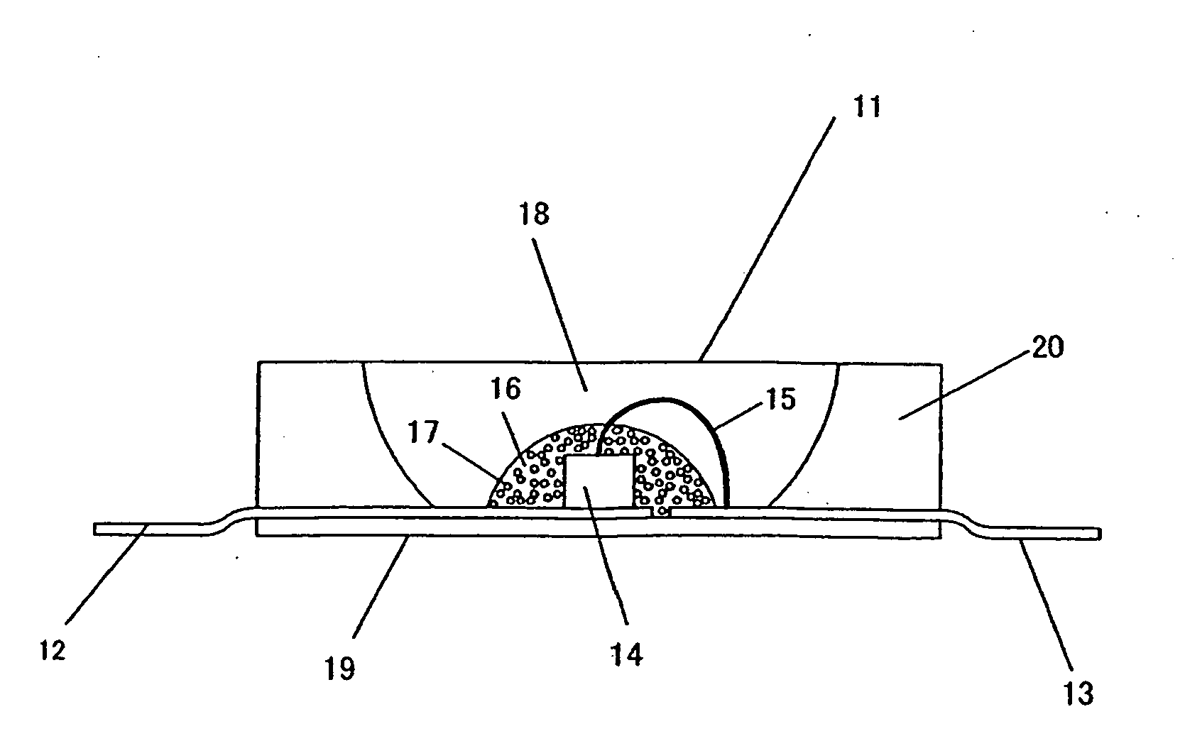
Image

Examples
example 1
[0216]Firstly, to synthesize Sr2Si3O2N4 without including activation metals M, there were weighed: 32.21 wt % of a silicon nitride powder having an averaged particle size of 0.5 μm, an oxygen content of 0.93 wt %, an α-type content of 92%; and 67.79 wt % of a strontium carbonate powder; and the powders were then mutually mixed for 30 minutes in the atmosphere by an agate pestle and an agate mortar; followed by natural drop of the obtained mixture into a crucible made of boron nitride through a sieve of 500 μm, thereby filling the powder into the crucible. The powder had a bulk density of about 22%. The crucible containing the mixed powder therein was set in an electric furnace of a black lead resistance heating type. There was conducted a firing operation by firstly bringing the firing environment to vacuum by a diffusion pump, heating from a room temperature up to 800° C. at a rate of 500° C. / hour, introducing nitrogen at a purity of 99.999 vol % at 800° C. to achieve a pressure of...
examples 2 to 37
[0224]Used as starting material powders were: a silicon nitride powder having an averaged particle size of 0.5 μm, an oxygen content of 0.93 wt %, and an α-type content of 92%; an aluminum nitride powder having a specific surface area of 3.3 m2 / g, and an oxygen content of 0.79%; and a silicon dioxide powder, aluminum oxide powder, strontium carbonate powder, magnesium oxide powder, calcium carbonate powder, barium carbonate powder, and europium oxide. To obtain inorganic compounds of designed compositions listed in Table 1, starting materials were mutually mixed at mixture compositions listed in Table 2, followed by firing in firing conditions listed in Table 3, as well as subsequent application of heat treatment in conditions listed in Table 3 as required, respectively. The inorganic compounds were thus synthesized, by the otherwise same procedures as those in the method for Example 1.
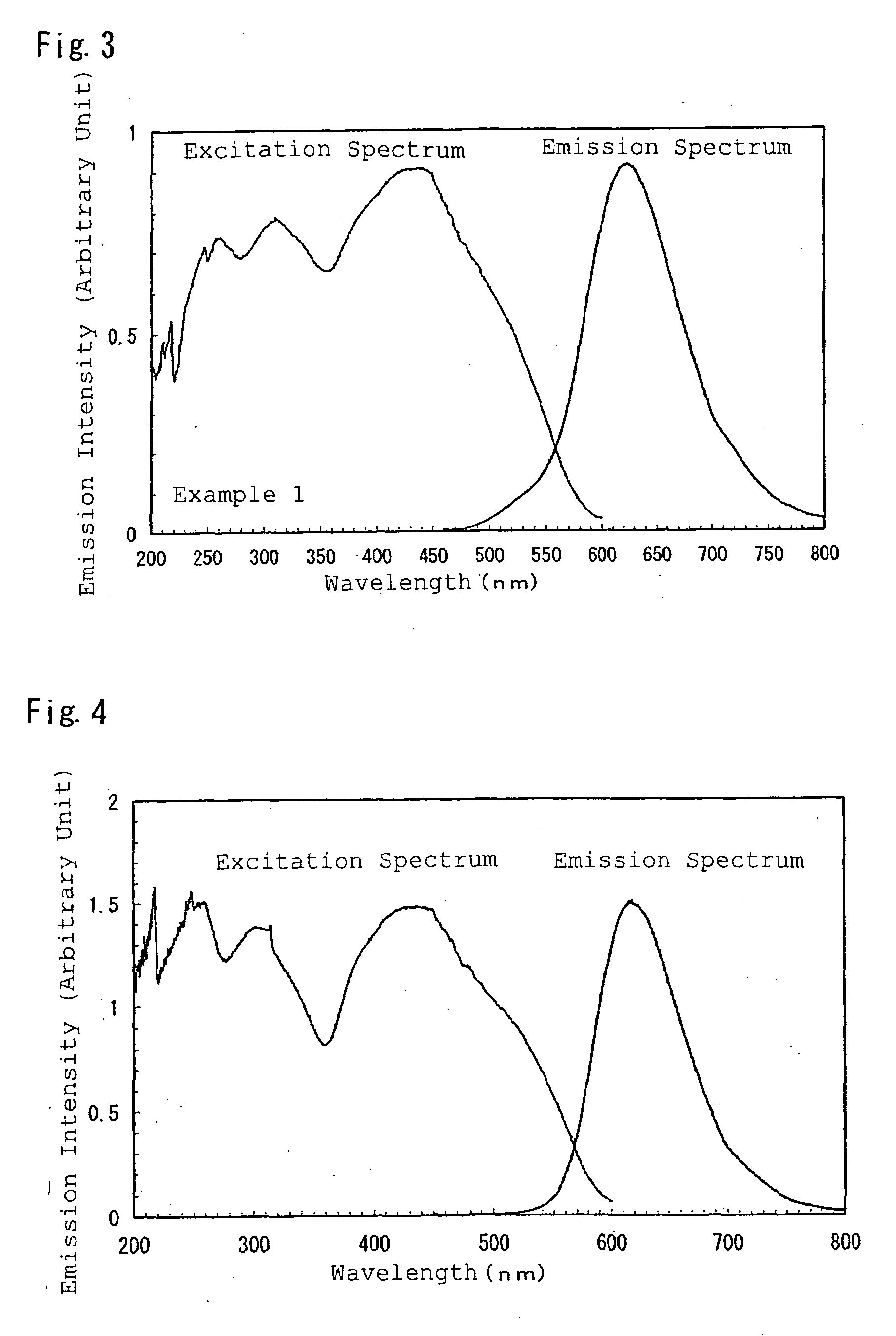
[0225]The powders were each measured by a spectrophotofluorometer to provide an emission spectrum ...
example 38
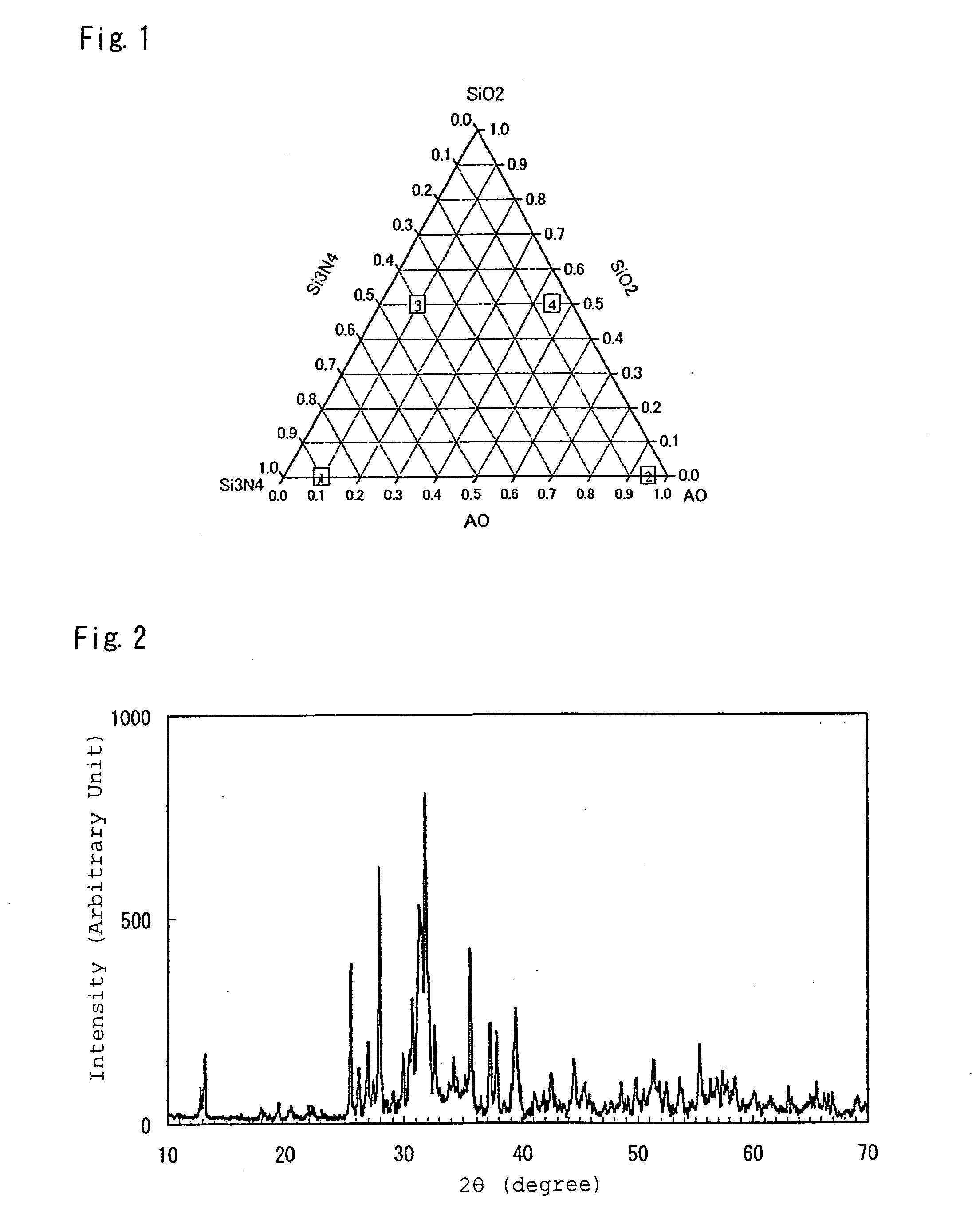
[0232]To obtain an inorganic compound Ca0.95Eu0.05Si5ON8 to be provided by activating a CaSi6ON8 crystal with Eu, there were mixed a silicon nitride powder, a calcium carbonate powder, and a europium oxide powder at a ratio of 72.977 mass %, 24.73 mass %, and 2.29 mass %, respectively, followed by firing for 2 hours at 1,800° C. in nitrogen at 0.45 MPa, thereby synthesizing a phosphor. The synthesis was conducted in the otherwise same procedures as those in the method for Example 1. According to X-ray diffractometry measurement, the obtained inorganic compound exhibited the same X-ray diffractometry pattern as the CaSi6ON8 crystal, and was thus confirmed to be an inorganic compound obtained by activating a CaSi6ON8 crystal with Eu.
[0233]The powder was measured by a spectrophotofluorometer to obtain an emission spectrum and an excitation spectrum, thereby resultingly obtaining a phosphor having properties of excitation spectrum and emission spectrum shown in FIG. 10.
PUM
| Property | Measurement | Unit |
|---|---|---|
| Temperature | aaaaa | aaaaa |
| Temperature | aaaaa | aaaaa |
| Percent by mass | aaaaa | aaaaa |
Abstract
Description
Claims
Application Information