
High-Temperature Dielectric Materials and Capacitors Made Therefrom

a dielectric material and capacitor technology, applied in the direction of fixed capacitor details, fixed capacitors, fixed capacitor terminals, etc., can solve the problems of capacitor temperature limitations, many power electronic systems are currently limited, and exceed the service temperature of electronic components, etc., to achieve high permittivity, low loss, and high resistivity

Inactive Publication Date: 2008-10-02
ALFRED UNIVERSITY +1
View PDF15 Cites 19 Cited by
  • Summary
  • Abstract
  • Description
  • Claims
  • Application Information

AI Technical Summary

Benefits of technology

[0011]The present invention is directed to a family of dielectrics based on sodium bismuth titanate, Na0.5Bi0.5TiO3 (NBT), and capacitors fabricated from these dielectrics. The dielectrics have moderately high permittivity, a broad range of temperature over which the permittivity is constant, and low loss and high resistivity over that temperature range. In addition the dielectrics should have little or no variation in permittivity with electric field and should exhibit low induced strain with applied electric field.
[0012]The present dielectrics may have moderate permittivity (>1000), low loss (<2%), high resistivity (>1010 ohm-m), and low variation in permittivity (±15%) over the temperature range −30 to 200° C. and / or over a relatively broad range of elevated temperatures, e.g., 200±100° C. to 400±100° C. Capacitors fabricated from these dielectrics may also have low loss (<2%), high insulation resistance, and low variation in capacitance (±15%) over the temperature range −30 to 200° C. and / or over a relatively broad range of elevated temperatures, e.g., from 150±100° C. to 350±100° C. Furthermore, capacitors fabricated from these dielectrics may have low field induced strain (<100 microstrains at 10 MV / m) and low variation in capacitance (±15%) with applied voltage up to field strengths of 10-15 MV / m.

Problems solved by technology

Many power electronic systems are currently limited by the low dielectric constant and / or low upper limit of operating temperature of commercially available capacitors and dielectric materials.
An increasing problem in certain systems today is exceeding the service temperature of electronic components because of the heat generated in current highly miniaturized and densely packed electronic circuits.
For example, temperature limitations of capacitors have been identified as the weak link in power electronic system reliability as manifest in motor drives, inverters / converters for switched reluctance starter / generator systems, DC to AC converters, DC to DC converters, and pulse forming networks.
While barium titanate has been used in high performance capacitor applications and has a wide operating temperature, ultimate performance is limited by its inherently low transition temperatures (−90, 0, 130° C.) and its semiconducting properties at elevated temperature.

Method used


Image

  • High-Temperature Dielectric Materials and Capacitors Made Therefrom
  • High-Temperature Dielectric Materials and Capacitors Made Therefrom
  • High-Temperature Dielectric Materials and Capacitors Made Therefrom

Examples


example 1

[0042]A dielectric having the composition Na0.2(Na0.5Bi0.5)0.75Ba0.05Ti0.8Ta0.2O3 (0.75NBT-0.05BT-0.2NTa) was prepared from reagent-grade oxide and carbonate powders. The powders were weighed according to their respective stoichiometric proportion and mixed on a ball mill with zirconia media in isopropyl alcohol for a period of 12-24 hours. The dried mixture was calcined at 750° C. for 2 hours. After calcination, binder was added at a level of 1% by weight and mixed for 6-8 hours with zircona media on a ball mill. The powder-binder mixture was dried, ground, and passed through a 100 mesh sieve to ensure uniform distribution of the binder.

[0043]Pellets consisting of 2-3 grams of powder were pressed using a laboratory Carver press and a ⅝″ die. The pellets were fired on zirconia setters with zirconia sand under them to prevent the pellets from adhering to the surface of the setter. They were fired at 1200° C. for 2 hours and the densities were above 90% theoretical. The fired pellets ...

example 2

[0047]Dielectrics having the composition 0.75NBT-5BT-20NTa were prepared with varying amounts of added Mn3O4 using the method described in Example 1. Resistivities were measured on the sintered discs at 200° C. with applied voltages 1-2 kV. The sample thicknesses ranged from 1-2 mm.

[0048]Resistivities are plotted in FIG. 5 as a function of wt % Mn3O4. It is seen that resistivities in excess of 1010 ohm-m can be obtained at 200° C. for a range 0.10-0.16 wt % Mn3O4 (0.07-0.12 wt % Mn).

example 3

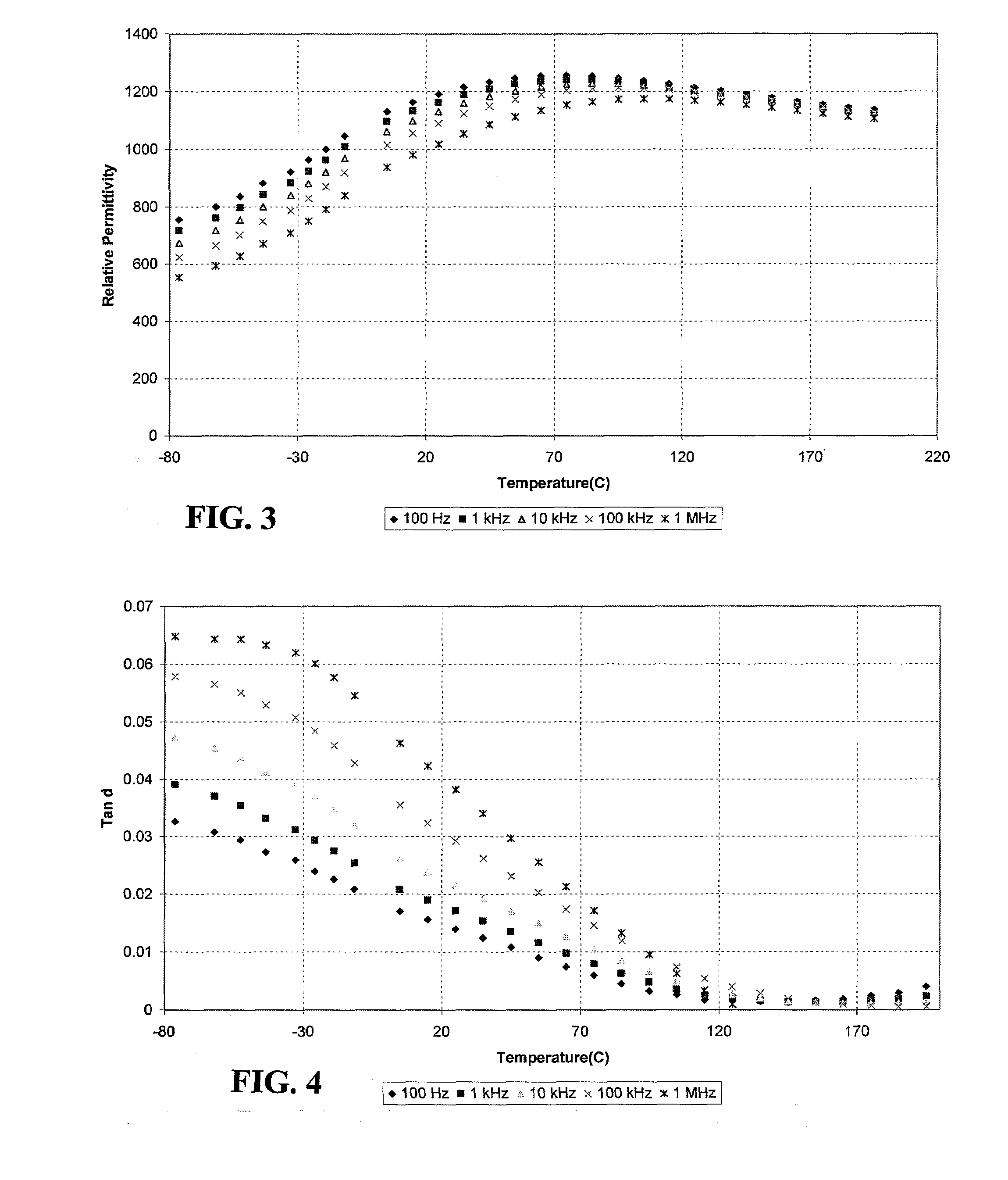
[0049]Dielectrics having the composition Na0.3(Na0.5Bi0.5)0.7Ti0.7Nb0.3O3 (70NBT-30NNb) were prepared using the method described in Example 1. Relative permittivity was measured as a function of temperature from −80 to 200° C. It is seen in FIG. 6 that the dielectric has a relative permittivity>500 at room temperature with near zero variation from −80 to 200° C. FIG. 7 illustrates loss (tanδ) properties as a function of temperature.


PUM

PropertyMeasurementUnit
Temperatureaaaaaaaaaa

Abstract

A ceramic dielectric composition suitable for preparing capacitors for use in high-temperature service conditions is disclosed. The ceramic material and capacitors made from it exhibit unique and heretofore unrealizable properties including low variation in capacitance with voltage up to high fields, low variation in capacitance with temperature over a broad temperature range, retained high permittivity at temperatures up to 200° C. and beyond, low loss, low field-induced strain and adequate capacitance to retain performance at very low service temperatures. The material is based on sodium bismuth titanate (NBT) with selected additions of substituents and dopants to broaden and flatten its dielectric response, lower loss, lower strain, lower voltage coefficient and increase resistivity.

Description

GOVERNMENT CONTRACT[0001]The United States Government has certain rights to this invention pursuant to Contract No. DTRA01-03-C-0031 awarded by the Defense Threat Reduction Agency.FIELD OF THE INVENTION[0002]The present invention relates to high-temperature dielectric compositions and capacitors fabricated from these dielectrics, and more particularly, relates to a family of dielectric compositions based on sodium bismuth titanate.BACKGROUND INFORMATION[0003]Many power electronic systems are currently limited by the low dielectric constant and / or low upper limit of operating temperature of commercially available capacitors and dielectric materials. Today's capacitors are typically limited in temperature capability to a maximum of 125° C., whereas many current commercial and military application temperatures range from −55 to 200° C. and even to 300° C. in some instances. Moreover, the application temperature refers to ambient service conditions and does not take into account interna...

Claims


Application Information

Patent Timeline
IPC IPC(8): H01G4/06
CPCC04B35/462C04B2235/3215C04B2235/3236C04B2235/3255C04B2235/3263C04B2235/3298C04B2235/768H01C7/025H01C7/045H01C7/115H01G4/1227
Inventor BRIDGER, KEITHCOOKE, ARTHUR V.SCHULZE, WALTER ARTHUR
Owner ALFRED UNIVERSITY
Learn More