Method for producing hydrogen gas separation material

Inactive Publication Date: 2008-10-02
NORITAKE CO LTD
View PDF3 Cites 13 Cited by
  • Summary
  • Abstract
  • Description
  • Claims
  • Application Information

AI Technical Summary

Benefits of technology

[0015]Because these silicon compounds (a) have a suitable molecular size, the method of the invention for forming a silica coat by CVD using the above compounds (a) as the silica source allows consistent production of a hydrogen gas separator with a pore size suitable for the separation of hydrogen gas. In addition, because these silicon compounds (a) already have Si—O—Si bonds or Si—N—Si bonds in the molecule, but no alkoxysilyl or Si—X groups (X is a halogen atom), CVD (such as counter diffusion CVD) employing these compounds as the silica source makes it possible to avoid excessive deposition.
[0016]In a preferred embodiment of the method for producing a hydrogen gas separator disclosed herein, a porous substrate in the form of a film supported by a porous support is used as the porous substrate. For example, a porous film with a pore diameter of about 2 nm to 20 nm (typically a porous film made of a ceramic

Problems solved by technology

However, in the conventional production of hydrogen gas separators (silica coat formation) by counter diffusion CVD, the quality of the resulting hydrogen gas separators has tended to be inconsistent.
One reason given for the inconsistent quality is that the thickness of silica coats formed by counter diffusion CVD (in other words,

Method used


Image

  • Method for producing hydrogen gas separation material
  • Method for producing hydrogen gas separation material
  • Method for producing hydrogen gas separation material

Examples


Example

Example 1

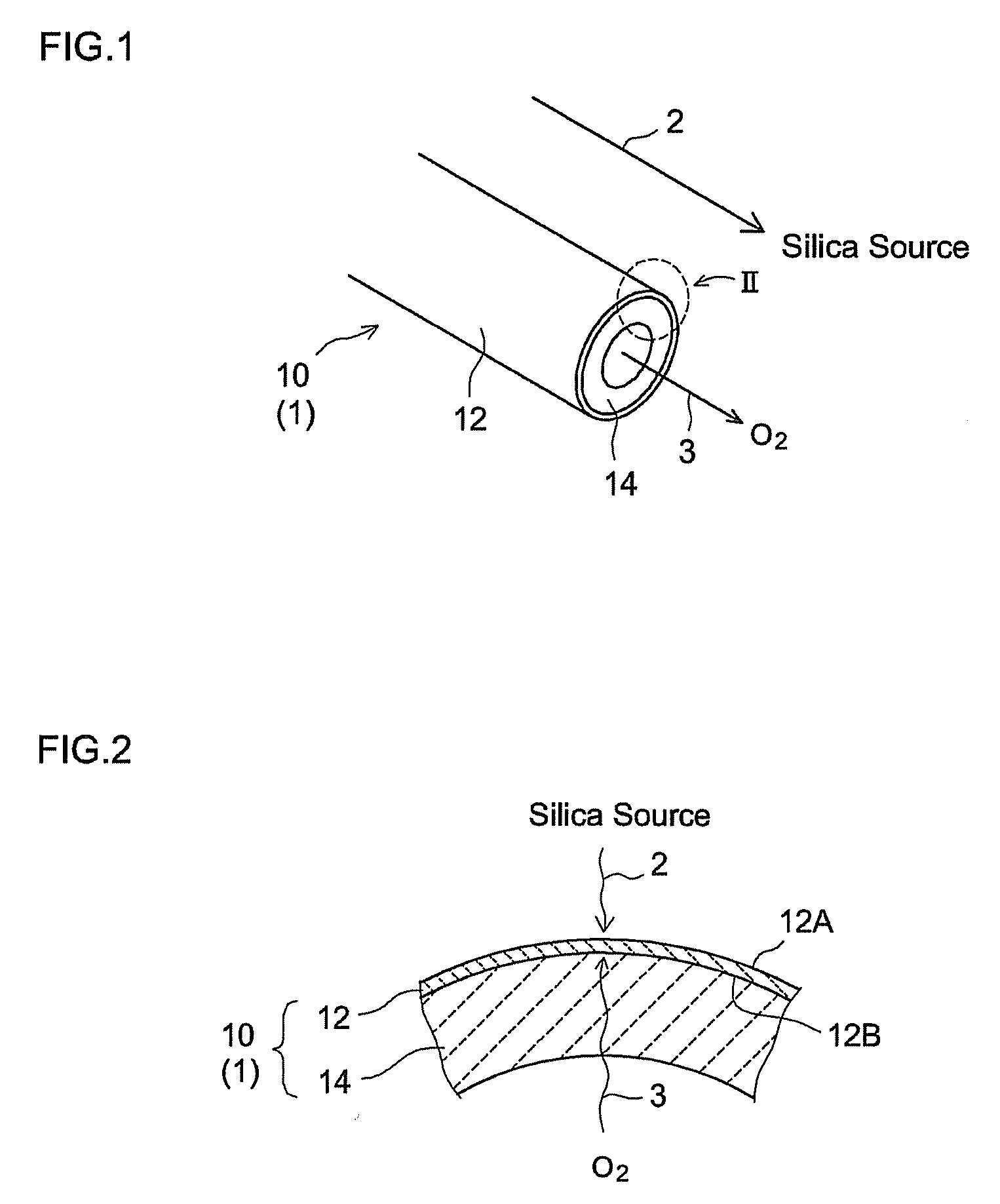
[0058]A hydrogen gas separator having the structure schematically illustrated in FIG. 1 was produced by the procedures given in FIG. 5. That is, α-alumina powder with a mean particle diameter of about 1 μm was kneaded along with water and an organic binder to prepare an extrusion molding paste. The paste was molded using a commercially available extruder, was dried, and was then fired in the atmosphere, to prepare a porous support 14 (α-alumina support) in a tubular shape (with outside diameter of 10 mm, inside diameter of 7 mm, and length of 50 mm) (step S10). The mean pore diameter of the support 14, as determined by general mercury penetration, was about 150 nm.

[0059]A porous film (porous substrate) 12 was then formed on the surface of the resulting a-alumina support 14 (step S20). In particular, a boehmite sol was produced through the hydrolysis of aluminum isopropoxide and acid peptization. The α-alumina support 14 (both ends of the tube were temporarily blocked so as ...

Example

Example 2

[0067]In this example, the reaction time (silica coat-producing time) during counter diffusion CVD was changed to 30 minutes. The hydrogen gas separator of Example 2 was in all other respects produced in the same manner as in Example 1.

[0068]The hydrogen gas separator was evaluated in the same manner as in Example 1. However, in this example, the hydrogen gas permeation activation energy was determined from an Arrhenius plot of the H2 permeability at 300° C., 500° C., and 600° C. The results are summarized in Table 2 along with an outline of the method of production and the structure of the hydrogen gas separator.

TABLE 2Example 2Porous substrate sintering temperature600° C.Silica sourceHMDSReaction temperature600° C.Reaction time30 minH2 permeation activation energy [kJ / mol]5.5H2 permeability (600° C.)7.3 × 10⁻⁷[mol / m2 · s · Pa]Permeability coefficient ratio (H2 / N2)2.8 × 10²

[0069]Table 2 shows that the activation energy, H2 permeability, and permeability coefficient ratio o...

Example

Example 3

[0070]A γ-alumina porous film (γ-alumina film) 12 was formed on the outer peripheral surface of an α-alumina support 14 in the same manner as in Example 1 except that the γ-alumina film (porous substrate) sintering temperature was changed to 800° C. The γ-alumina film 12 was about 2 μm thick, with a peak pore diameter of 8 nm to 10 nm, as determined by common nitrogen absorption. The γ-alumina film 12 obtained as a result of the firing process at 800° C. is sometimes referred to below as “γ-alumina substrate (800° C.)”. The hydrogen gas separator of Example 3 was produced by carrying out counter diffusion CVD in the same manner as in Example 1 except for the use of the γ-alumina substrate (800° C.) instead of the γ-alumina substrate (600° C.). The hydrogen gas separator so obtained was evaluated in the same manner as in Example 1. The results are summarized in Table 3 along with an outline of the method of production and the structure of the hydrogen gas separator.

TABLE 3Ex...


PUM

PropertyMeasurementUnit
Temperatureaaaaaaaaaa
Pore sizeaaaaaaaaaa

Abstract

The invention provides a method for consistently producing a hydrogen gas separator with a good performance balance. The method includes the process for preparing a porous substrate and the process for forming a silica coat on the substrate by chemical vapor deposition in which a reaction is brought about between a silica source provided to one side of the substrate and an oxygen-containing gas supplied to the other side of the substrate. The vapor deposition process is carried out using as the silica source a silicon compound (a) with Si-Z-Si bonds (Z is O or N) in the molecule.

Description

RELATED APPLICATION(S)[0001]The application claims priority from Japanese Patent Application No. 2007-088049 filed on Mar. 29, 2007, the entire content of which is incorporated herein by reference.BACKGROUND OF THE INVENTION[0002]1. Field of the Invention[0003]The present invention relates to a method for the production of a hydrogen gas separator.[0004]2. Description of the Related Art[0005]Hydrogen gas separators are known to be used for the supply of hydrogen to fuel cells, catalytic membrane reactors, and the like. A typical method known for producing such hydrogen gas separators, for example, includes a process for forming a silica coat on a porous substrate composed of a ceramic material to reduce the size of the openings of the pores in the substrate. Typical examples of methods for forming such silica coats include chemical vapor deposition (CVD) and the sol gel method.[0006]The documents related to the formation of silica coats by CVD include Japanese Patent Application Pub...

Claims


Application Information

Patent Timeline
IPC IPC(8): C23C16/00
CPCB01D53/228B01D67/0072B01D71/027B01D2257/108C01B3/503C01B2203/0405C01B2203/0465C01B2203/0495C04B41/009C04B41/52C04B41/89C04B2111/00801C23C16/045C23C16/402C04B41/4537C04B41/4582C04B41/5031C04B41/4539C04B41/522C04B41/4531C04B41/5035C04B35/10C04B35/00C04B38/0054B01D2325/20B01D2325/22
Inventor YOSHINO, YASUSHI
Owner NORITAKE CO LTD
Why Eureka
Try Eureka