Carbon dioxide removal from whole blood by photolytic activation

a technology of photolysis and activated carbon dioxide, which is applied in the field of photolysis equipment, can solve the problems of insufficient technology, no one is believed, and insufficient yield, safety, and ease of us

Inactive Publication Date: 2009-01-15
BATTELLE MEMORIAL INST
View PDF44 Cites 32 Cited by
  • Summary
  • Abstract
  • Description
  • Claims
  • Application Information

AI Technical Summary

Benefits of technology

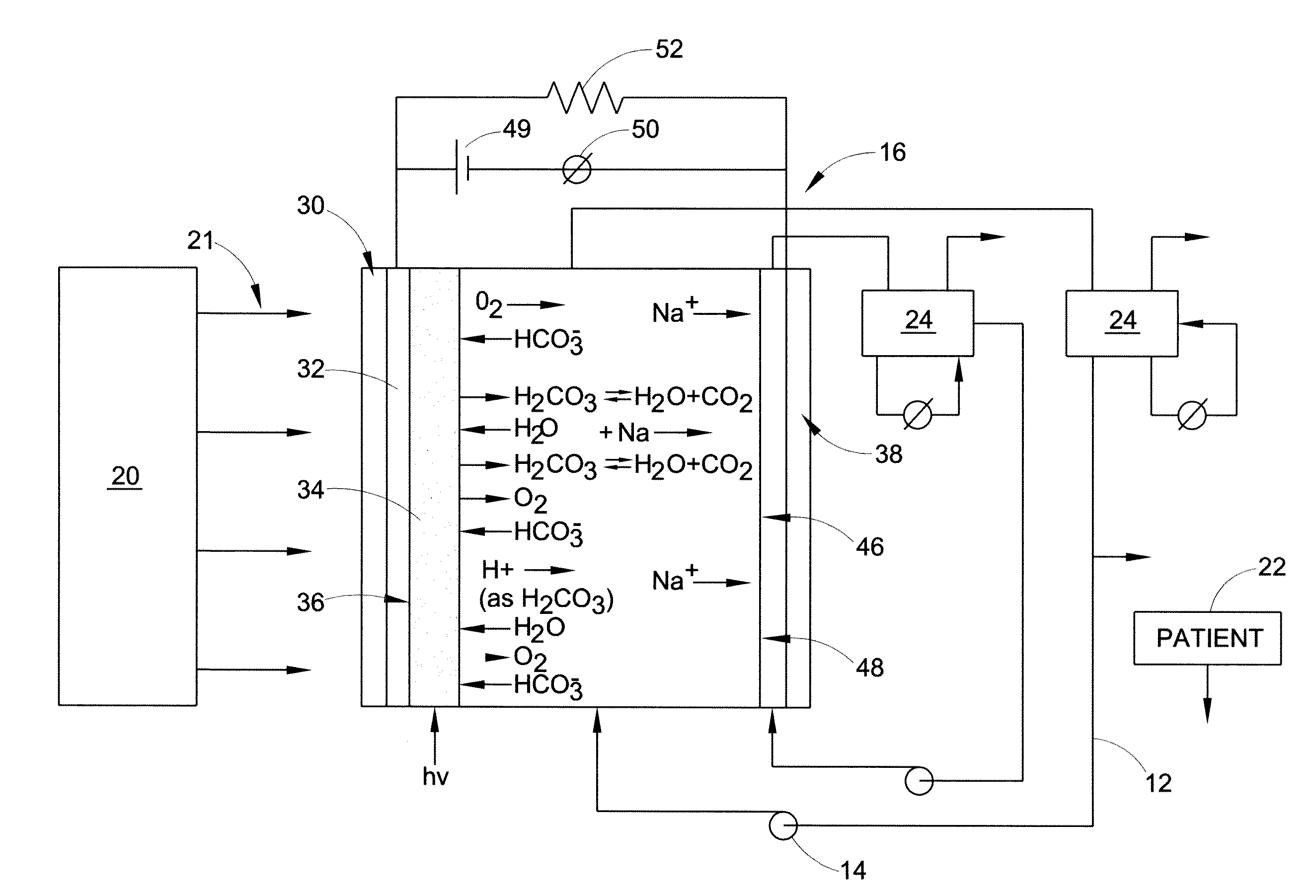
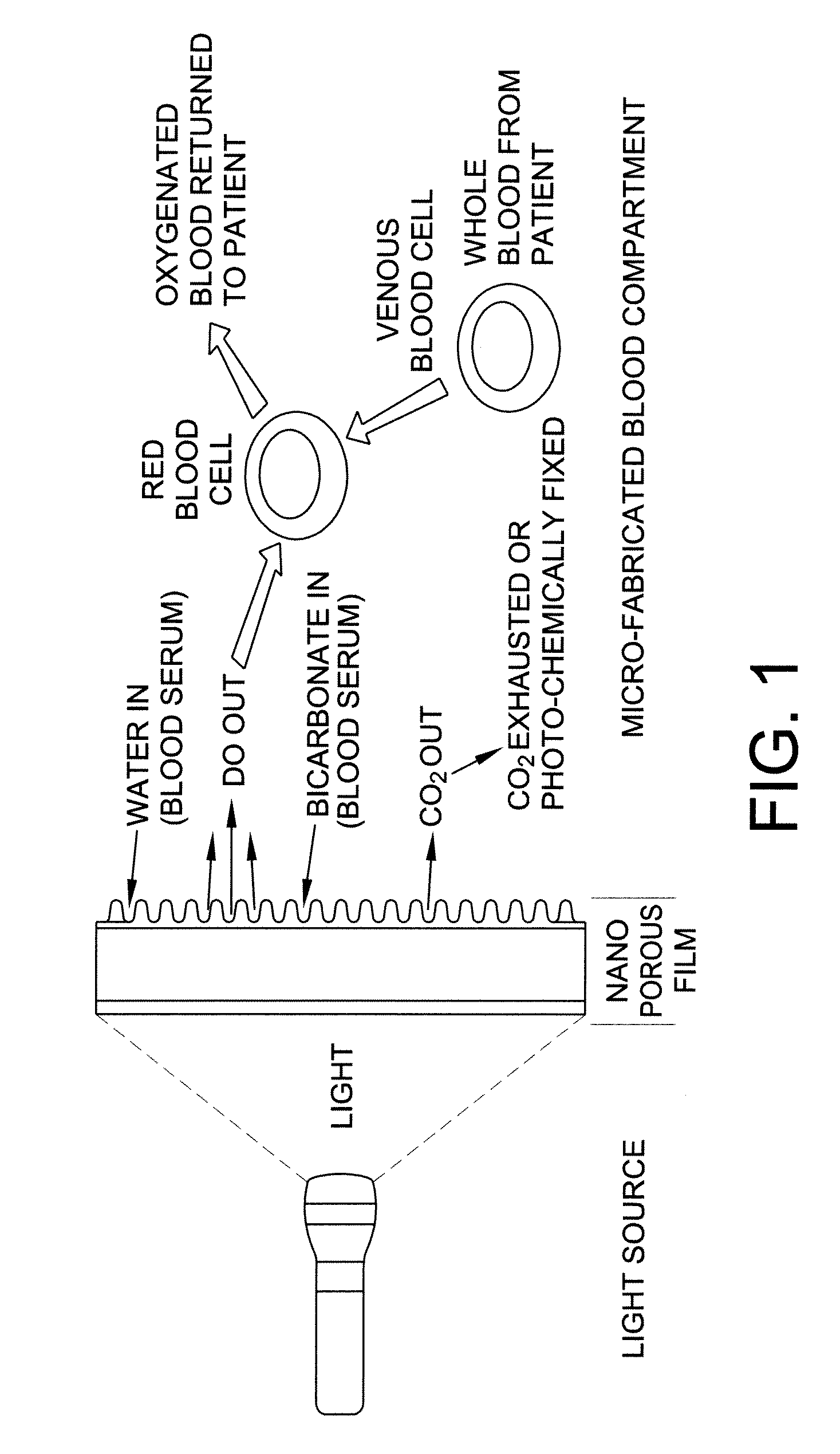
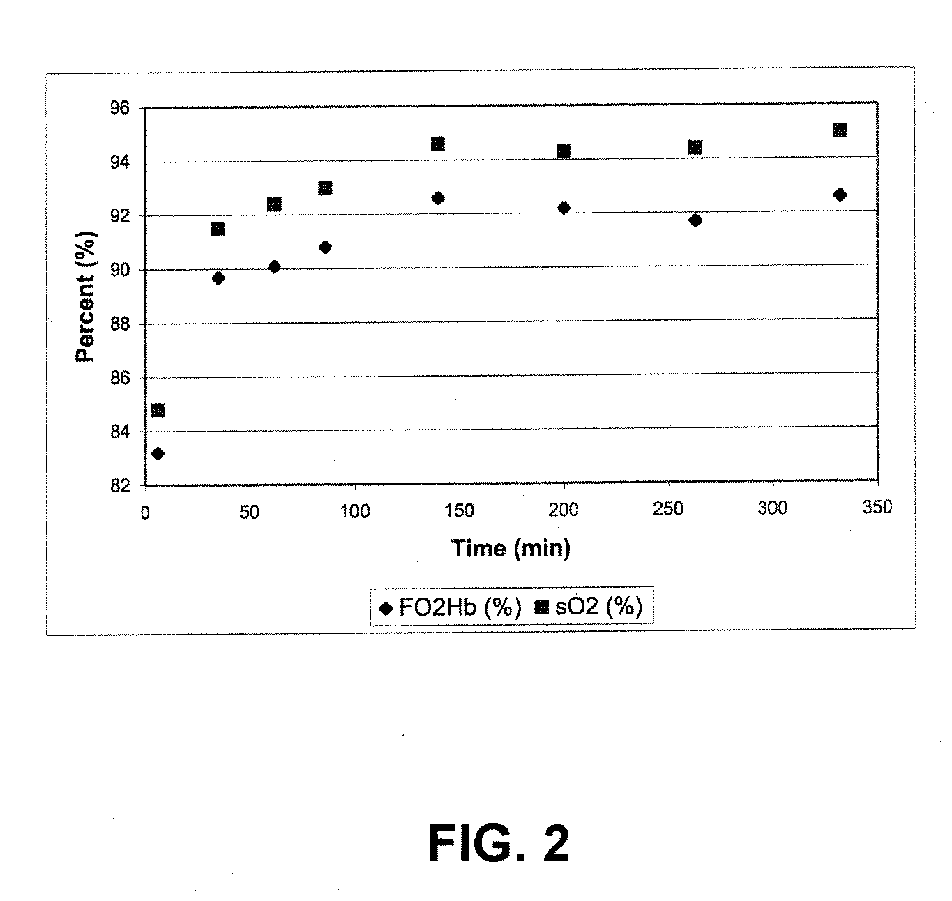
[0009]Disclosed herein, in various embodiments, is a process and apparatus for using photolytic energy to generate dissolved oxygen from whole blood, thus providing an increase of oxyhemoglobin as a function of the metal oxide (i.e., TiO2) surface illumination. In one embodiment, the disclosure includes flowing mixed arterial-venous whole blood in a recirculating loop in a device having a nanocrystalline metal oxide TiO2 thin film. Following light exposure of the metal oxide or TiO2 film only (while not exposing the blood to the light), the fraction of oxy-hemoglobin in the blood rapidly increases and remains substantially stable thereafter. The fraction of dissolved oxygen contained in the serum phase of the blood increases in a parallel manner with oxyhemoglobin as a result of light induction, indicating that near complete oxygenation of the blood's hemoglobin content has been achieved. The present disclosure demonstrates that it is feasible to photolytically oxygenate the hemoglobin contained in whole blood with oxygen derived from the blood's own water content by only providing energy at mild conditions.

Problems solved by technology

This is largely due to a lack of emerging treatments, and inadequate technology for providing intermediate (“bridge” therapy) or long-term respiratory support.
However, none are believed, to this point, to provide sufficient yield, safety, and ease of use to support broad clinical deployment.
However, the large discrepancy between the numbers of donors and recipients, the low yield of usable lungs, and the absence of temporizing methods for patients awaiting transplantation, make this option outside the reach of many patients.
The principal weakness, however, of these systems is that they require the presence of major diffusion boundary layers, which results in slowed mass transport and the need for a large surface area to achieve sufficient flux of gases.

Method used


Image

  • Carbon dioxide removal from whole blood by photolytic activation
  • Carbon dioxide removal from whole blood by photolytic activation
  • Carbon dioxide removal from whole blood by photolytic activation

Examples


example 1

[0119]This example illustrates the fabrication of photoactive layers. Oxide materials were added to a substrate using a spin coating technique. Glass slides containing the conducting layer were placed on a vacuum. For the TiO2 coating, 0.5 g of the acid treated material was added to 40 ml isopropanol and mixed for 30 minutes. 0.050 ml H2O and 0.100 ml titanium(IV) tetra(isopropoxide) (TTIP), a sol-gel reagent, was added to this solution. After mixing for 30 minutes, the solution was added drop-wise to the rotating substrate for a total volume of about 12 ml. In the case of the constructs containing MnO2, following the addition of 9 ml of TiO2 slurry, 0.20 g MnO2 was added to the remaining slurry. Exactly four ml of the resulting solution was then added drop-wise to the substrate at spin coating conditions. As a modification of this technique, RuO2 / Pt doped TiO2 (0.125 g) was added to 10 ml isopropanol. After 15 minutes of mixing, 50 uL water and 25 uL TTIP was added and allowed to m...

example 2

[0120]In addition to batch cells, a flow-through test cell was constructed to associate flowing liquids (such as blood) with photolytic output. A modified FM01-LC Electrolyser, operating in a divided cell mode with a Nafion™ cation exchange membrane was used. The anode was optically transparent, and illumination was achieved side-on by UV light (354 nm) using a filter and UVA fiber optic lamp source. The catholyte was Locke's-Ringer solution, and the anolyte fresh whole bovine blood containing anticoagulant. The photolytic surface was TiO2 on a quartz plate. Fluids were maintained at 37° C. using an in-line heat exchange jacket, and flow was 80 cc / min by a peristaltic pump. The flow-through cell consisted of a 3 ml photolytic chamber, with a single active surface of vacuum deposited Ti metal, a coating of TiO2 (anatase) and optionally a MnO2 layer. These films were prepared as described above for the batch test films, except on larger glass and quartz substrates (effective area ˜5 i...

example 3

[0122]This example illustrates real-time measurement of dissolved oxygen (DO): A liquid phase in line reaction chamber was used to monitor dissolved oxygen production. This device utilized a Clark Electrode to measure dissolved oxygen (DO). A two-point calibration procedure was used to calibrate the dissolved oxygen sensor. Dasse K A, Monzyk B F, Burckle E C, Busch J R, Gilbert R J., Development of a photolytic artificial lung: Preliminary concept validation, ASAIO Journal, 48:556-563, 2003. A low bias voltage was applied to the cell through a DC power source, sufficient to insure proper anode-to-cathode electron flow direction, to promote immediate removal of photo-generated electrons, but insufficient to drive electrochemical side reactions, as evidenced by the lack of current flow in the absence of illumination. Dasse K A, Monzyk B F, Burckle E C, Busch J R, Gilbert R J., Development of a photolytic artificial lung: Preliminary concept validation, In press, ASAIO Journal, 2003. E...


PUM


Abstract

Apparatus and methods for removing carbon dioxide from whole blood. Hydrogen ions are generated from water in the blood, resulting in the formation and release of carbon dioxide from the blood.

Description

RELATED APPLICATIONS[0001]The present application is a continuation application of U.S. patent application Ser. No. 11 / 130,047, now U.S. Pat. No. 7,399,717. The disclosure of this application is hereby fully incorporated by reference.[0002]This application is also related to U.S. patent application Ser. Nos. 10 / 485,455; 10 / 485,476; and, 10 / 485,934, all filed on Jan. 30, 2004. The disclosures of those applications are also fully incorporated herein by reference.BACKGROUND[0003]The present disclosure, in various embodiments, is directed to a photolytic apparatus that utilizes light energy to achieve physiological gas exchange in whole blood, such as in the blood stream of a patient experiencing respiratory difficulties, whole blood utilized to transport organs, etc., and to a photolytic cell or module used for the same. The disclosure finds particular applications in conjunction with the field of artificial organs and the medical arts. However, it is to be appreciated, that the embodi...

Claims


Application Information

Patent Timeline
Patent Type & Authority Applications(United States)
IPC IPC(8): A61M1/32A01N1/02A61K35/14A01N1/00A61M1/34A61M1/36
CPCA61M1/32A61M1/3683A61M1/3681A61M1/327
Inventor MONZYK, BRUCE F.BURCKLE, ERIC C.
Owner BATTELLE MEMORIAL INST
Why Eureka
Try Eureka