
Catalyst and Catalyst Structure for Reduction of Nitrogen Oxides, and Method for Catalytic Reduction of Nitrogen Oxides

a catalyst and nitrogen oxide technology, applied in physical/chemical process catalysts, metal/metal-oxide/metal-hydroxide catalysts, separation processes, etc., can solve the problems of remarkable fuel efficiency drop, deterioration of catalytic activity at low temperatures, and disadvantages of conventional methods, and achieve high durability

Inactive Publication Date: 2009-04-02
VALTION TEKNILLINEN TUTKIMUSKESKUS +1
View PDF3 Cites 30 Cited by
  • Summary
  • Abstract
  • Description
  • Claims
  • Application Information

AI Technical Summary

Benefits of technology

The invention provides a catalyst for reducing nitrogen oxides in exhaust gas from combustion with fuel. The catalyst is designed to be highly durable and effective in a wide temperature range, even in the presence of oxygen, sulfur oxides, or water. The catalyst can be supported on an inactive substrate and includes an outer layer comprising a solid acid and / or an oxide of at least one element selected from vanadium, tungsten, molybdenum, copper, iron, cobalt, nickel, and manganese, an inner layer comprising at least one noble metal catalyst component selected from platinum, rhodium, palladium, and an oxide thereof, and a catalyst component comprising ceria or praseodymium oxide or a mixture of oxides of at least two elements selected from cerium, zirconium, praseodymium, neodymium, terbium, samarium, gadolinium, and lanthanum. The catalyst is effective in reducing nitrogen oxides in exhaust gas from combustion with fuel and can be used in a variety of applications.

Problems solved by technology

However, these conventional methods have their own disadvantages.
The latter method, for example, when it uses ammonia as a reducing agent, involves a problem that ammonia reacts with SOx in the exhaust gases to form salts, resulting in deterioration in catalytic activity at low temperatures.
This means that substantial reduction of NOx needs a large quantity of a reducing agent, and hence resulting in remarkable fall of fuel efficiency.
However, the catalysts that have been conventionally known for direct decomposition of NOx have not yet been put to practical use due to their low decomposition activity.
However, it has been found that even the H-type zeolite has no sufficient reduction activity, and particularly the zeolite catalyst is rapidly deactivated on account of dealumination of the zeolite structure when water is contained in the exhaust gas.
However, it has been found that the catalyst has a high activity for oxidation, but a low activity for selective reduction of NOx, so that the catalyst has a low conversion rate of nitrogen oxides to nitrogen.
In addition, the catalyst involves a problem that it is deactivated rapidly in the presence of sulfur oxides.
This makes it difficult for such lean NOx catalysts to be practically used.
However, there is a problem that in the presence of SOx, the catalytic system deteriorates drastically due to the irreversible absorption of SOx at NO2 absorption sites on the alkali compound under either the lean or the rich conditions.

Method used

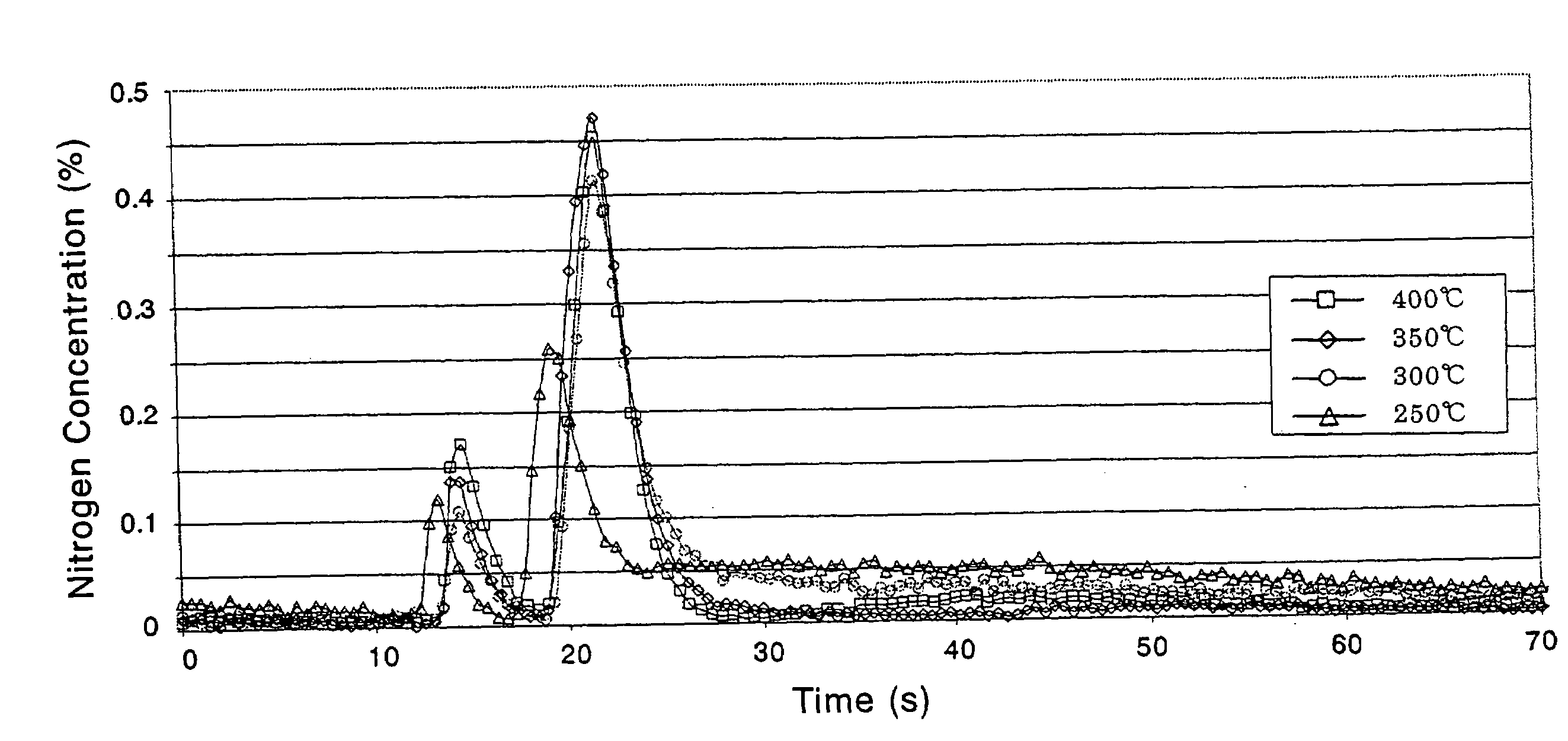
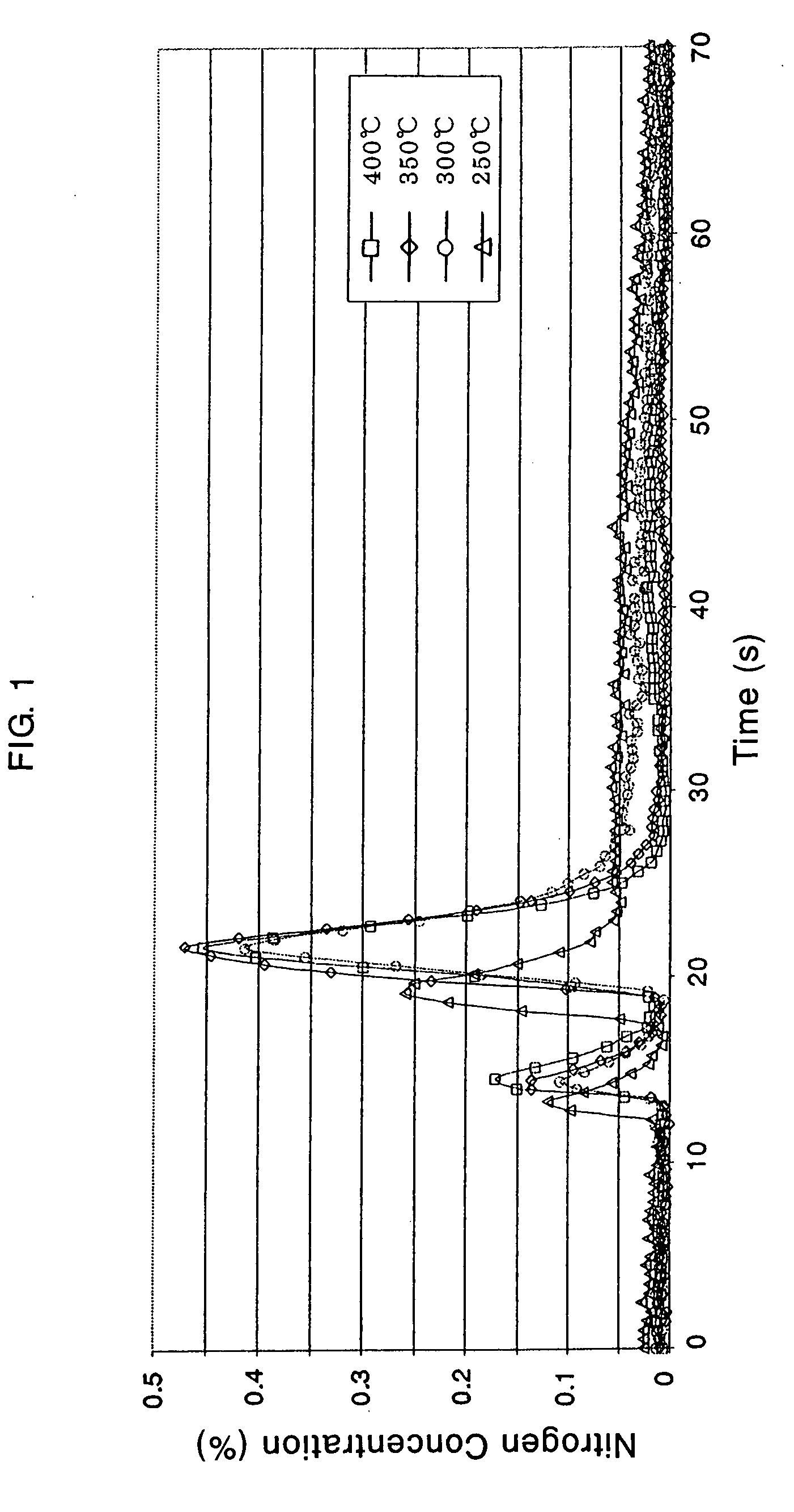
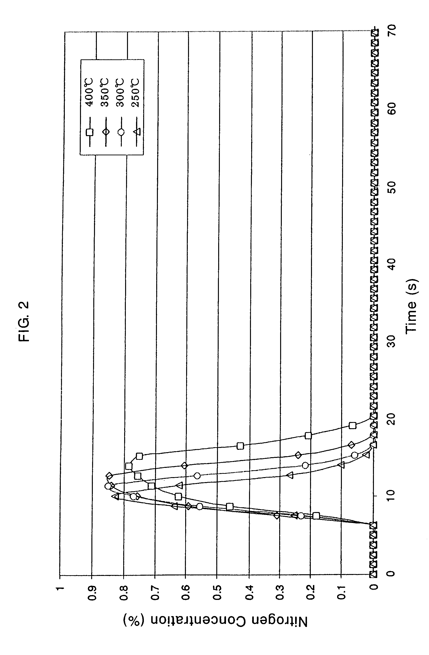

Image

  • Catalyst and Catalyst Structure for Reduction of Nitrogen Oxides, and Method for Catalytic Reduction of Nitrogen Oxides
  • Catalyst and Catalyst Structure for Reduction of Nitrogen Oxides, and Method for Catalytic Reduction of Nitrogen Oxides
  • Catalyst and Catalyst Structure for Reduction of Nitrogen Oxides, and Method for Catalytic Reduction of Nitrogen Oxides

Examples


preparation example 1

[0078]151.37 g of cerium nitrate (Ce(NO3)3.6H2O) was dissolved in 1000 ml of ion-exchanged water to prepare an aqueous solution. 0.1-N ammonia water was added to the aqueous solution to neutralize and hydrolyze the cerium ions, and the resulting slurry was aged for one hour. The product was separated from the slurry by filtering, dried at a temperature of 120° C. for 24 hours, and then calcined in the air at a temperature of 500° C. for three hours to obtain ceria powder (having a specific surface area of 138 m2 / g).

preparation example 2

[0079]164.31 g of cerium nitrate (Ce(NO3)336H2O) and 4.47 g of praseodymium nitrate (Pr(NO3)3.6H2O) were dissolved in 1000 ml of ion-exchanged water to prepare an aqueous solution. 0.1-N ammonia water was added to the aqueous solution to neutralize and hydrolyze the cerium salt and praseodymium salt, and the resulting slurry was aged for one hour. The resulting product was separated from the slurry by filtering, dried at a temperature of 120° C. for 24 hours, and then calcined in the air at a temperature of 500° C. for three hours to obtain ceria / praseodymium oxide composite oxide powder (having an oxide weight ratio of 95 / 5 and a specific surface area of 182 m2 / g).

preparation example 3

[0080]164.31 g of cerium nitrate (Ce(NO3)3.6H2O), 2.24 g of praseodymium nitrate (Pr(NO3)3.6H2O) and 3.98 g of lanthanum nitrate (La(NO3)3.6H2O) were dissolved in 1000 ml of ion-exchanged water to prepare an aqueous solution. 0.1-N ammonia water was added to the aqueous solution to neutralize and hydrolyze the cerium salt, praseodymium salt and lanthanum salt, and the resulting slurry was aged for one hour. The resulting product was separated from the slurry by filtering, dried at a temperature of 120° C. for 24 hours, and then calcined in the air at a temperature of 500° C. for three hours to obtain ceria / praseodymium oxide / lanthanum oxide composite oxide powder (having an oxide weight ratio of 95 / 2.5 / 2.5 and a specific surface area of 180 m2 / g).


PUM

PropertyMeasurementUnit
temperatureaaaaaaaaaa
concentrationaaaaaaaaaa
catalytic activityaaaaaaaaaa

Abstract

The invention provides a catalyst and a catalyst structure for catalytic reduction of nitrogen oxides contained in exhaust gas wherein fuel is supplied and subjected to combustion under periodic rich / lean conditions and the resulting exhaust gases are brought into contact therewith, which catalyst comprises:an outer catalyst layer comprising an outer catalyst component A which comprises at least one selected from a solid acid, and a solid acid supporting oxides and / or ions of at least one element selected from vanadium, tungsten, molybdenum, copper, iron, cobalt, nickel and manganese, andan inner catalyst layer comprising an inner catalyst component which comprises at least one noble metal catalyst component B selected from platinum, rhodium, palladium and an oxide thereof and a catalyst component C comprising ceria or praseodymium oxide or a mixture of oxides and / or a composite oxide of at least two elements selected from cerium, zirconium, praseodymium, neodymium, terbium, samarium, gadolinium and lanthanum. The invention further provides a method for catalytic reduction of nitrogen oxides by contacting the nitrogen oxides with the catalyst.

Description

TECHNICAL FIELD[0001]The invention relates to catalytic reduction of nitrogen oxides (which mainly comprise NO and NO2, and will be referred to as NOx hereunder), that is, the invention relates to a catalyst for reduction of NOx and a method for catalytic reduction of NOx contained in exhaust gas using such a catalyst. More particularly, the invention relates to a catalyst for reduction of NOx contained in exhaust gas wherein fuel is supplied to a combustion chamber of a diesel engine or a gasoline engine and subjected to combustion with periodic rich / lean excursions and the resulting exhaust gas is brought into contact with the catalyst. The invention also relates to a method for catalytic reduction of nitrogen oxides contained in exhaust gas using such a catalyst. The catalyst and method of the invention are suitable for reducing and removing harmful nitrogen oxides contained in exhaust gas, e.g., from engines of automobiles.[0002]In particular, the invention relates to a catalyst...

Claims


Application Information

Patent Timeline
Patent Type & Authority Applications(United States)
IPC IPC(8): F01N3/20B01D53/86B01D53/94B01J23/10
CPCB01D53/9422B01D2255/1021B01J2523/00B01J37/033B01J37/0248B01J37/0246B01J37/0244B01J35/1019B01D2255/1023B01D2255/1025B01D2255/2063B01D2255/2065B01D2255/2066B01D2255/2068B01D2255/20715B01D2255/9022B01D2255/908B01D2255/91B01D2258/012B01J23/002B01J23/10B01J23/63B01J23/64B01J23/8933B01J29/18B01J29/7007B01J29/76B01J2523/37B01J2523/3712B01J2523/48B01J35/615
Inventor NAKATSUJI, TADAOSUZUKI, NORIOOHNO, HIROSHISATO, NAOHIRO
Owner VALTION TEKNILLINEN TUTKIMUSKESKUS
Learn More