Rod Sealing System

a sealing system and rod technology, applied in the direction of brake systems, machines/engines, other chemical processes, etc., can solve the problems of reducing mechanical strength, affecting the sealing effect, so as to improve the durability against leakage due to a loss of resilience, the effect of satisfactory follow-up to eccentricity

Active Publication Date: 2009-07-02
UNIMATEC CO LTD +1
View PDF13 Cites 15 Cited by
  • Summary
  • Abstract
  • Description
  • Claims
  • Application Information

AI Technical Summary

Benefits of technology

[0021]In the structure of the present system, so long as the interference of buffer ring capable of attaining the pressure load-buffering effect on the rod seal, in the case of without any damage, etc., changes in the interference due to a loss of resilience are larger than changes in the interference due to abrasion, suggesting that the loss of resilience can be regarded as particularly important for the buffer ring in the rod sealing system.
[0022]In other words, the present thermoplastic polyurethane molding product has high heat resistance and compression set characteristics, particularly distinguished compression set characteristics at high temperatures such as 1000-120° C., and also has satisfactory follow-up to eccentricity, and thus can be used as a suitable sealing material or packing material.
[0023]When such a sealing material or packing material made of the thermoplastic polyurethane molding product is used as a buffer ring in a rod sealing system, that is, a rod sealing system comprising the buffer ring, a rod seal, and a dust seal, as used in oil hydraulic cylinders, etc. as actuators in construction machinery or transport vehicles, a durability against leakage due to a loss of resilience can be improved, thereby enhancing the heat-resistant limit temperature. Furthermore, the higher the temperature, or the longer the sliding distance, the more significantly the rate of loss of resilience or the compression set characteristics can be improved.
[0024]More specifically, use of such a heat-treated thermoplastic polyurethane molding product as a buffer ring can improve the durability against a loss of resilience due to a thermal factor, thereby maintaining the temperature- and pressure-reducing effect as a function of buffer ring, and it is expectable that suppression of a direct pressure load on the rod seal can attain reduction in surface pressure of rod seal, and also a heat generation-reducing effect. Thus, abrasion of rod seal can be suppressed, thereby increasing the service life of the rod sealing system. Furthermore, when the heat-treated thermoplastic polyurethane molding product is used as a buffer ring, such desired effects can be obtained, even if the rod seal is made of (hydrogenated) NBR, and the dust seal is made of general-purpose polyurethane.

Problems solved by technology

When the rod sealing system of the afore-mentioned Patent Literature 1 is used, for example, at a service temperature of 120° C., such a problem as considerable decrease in the sealability has been encountered.
However, due to a loss of resilience caused by a decrease in mechanical strength or due to reduction in interference caused by an increase in abrasion, under conditions in excess of the service limit temperature or in continuous working under such conditions, buffer ring B will fail to function fully (see Paragraph of afore-mentioned Patent Literature 1).
However, the heat resistance and mechanical characteristics of thermoplastic polyurethane for use in the buffer ring B depend on physical restrictions imposed by hydrogen bonds, etc. of hard segments in the polymer chain, and thus have been so far not always satisfactory under the influence of softening or melting point, or heat stability of the hard segment.
In that case, there is such a problem as an increase in the hardness of molding product resulting in loss of softness.
Attempts have been so far made to replace the components of the hard segment with more rigid ones to improve the heat resistance or compression set characteristics, but have been found not satisfactory.
For example, Patent Literature 2 or 3 discloses use of 4,4′-biphenyldiol compounds having a molecule structure with good symmetry and rigidity, as a chain lengthening agent, where the resulting thermoplastic polyurethane has good mechanical characteristics, but suffers from a large reduction in the modulus of elasticity due to increased temperature, and also from an unsatisfactory heat resistance.
When p-phenylene diisocyanate as disclosed in Patent Literature 4 is used as a diisocyanate compound, thermoplastic elastomers having distinguished thermal deformation resistance and compression set characteristics can be obtained, but the diisocyanate compound is hard to handle because of a high melting point and also sublimation property, so there is such a problem as thermoplastic elastomers of desired constant quality are hard to obtain.
Thus, it is now difficult to satisfy the mechanical characteristics, heat resistance and compression set characteristics at the same time by changing the hard segment content or composition ratio of raw material urethane.
To obtain a satisfactory effect, however, it is necessary to add a relatively large amount, for example, about 10 to about 30 parts by weight, or more, of the reinforcing agent to 100 parts by weight of thermoplastic polyurethane, sometimes giving rise to such problems as decreases in the rubber elasticity, rigidity, surface flatness, and increases in the specific gravity, etc., of the molding products.
However, the heat resistance of thermoplastic polyurethane is largely dependent also on physical structure such a molecule arrangement (orderly arrangement of hard phases for improving the packing), besides the chemical structures such as cross-linking structure, and thus it is hard to obtain physical stabilities such compression set characteristics only by the method disclosed in Patent Literature 5.

Method used


Image

  • Rod Sealing System
  • Rod Sealing System

Examples


example

Evaluation of Rate of Loss of Resilience of Buffer Ring

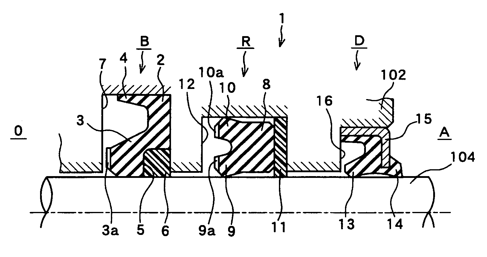
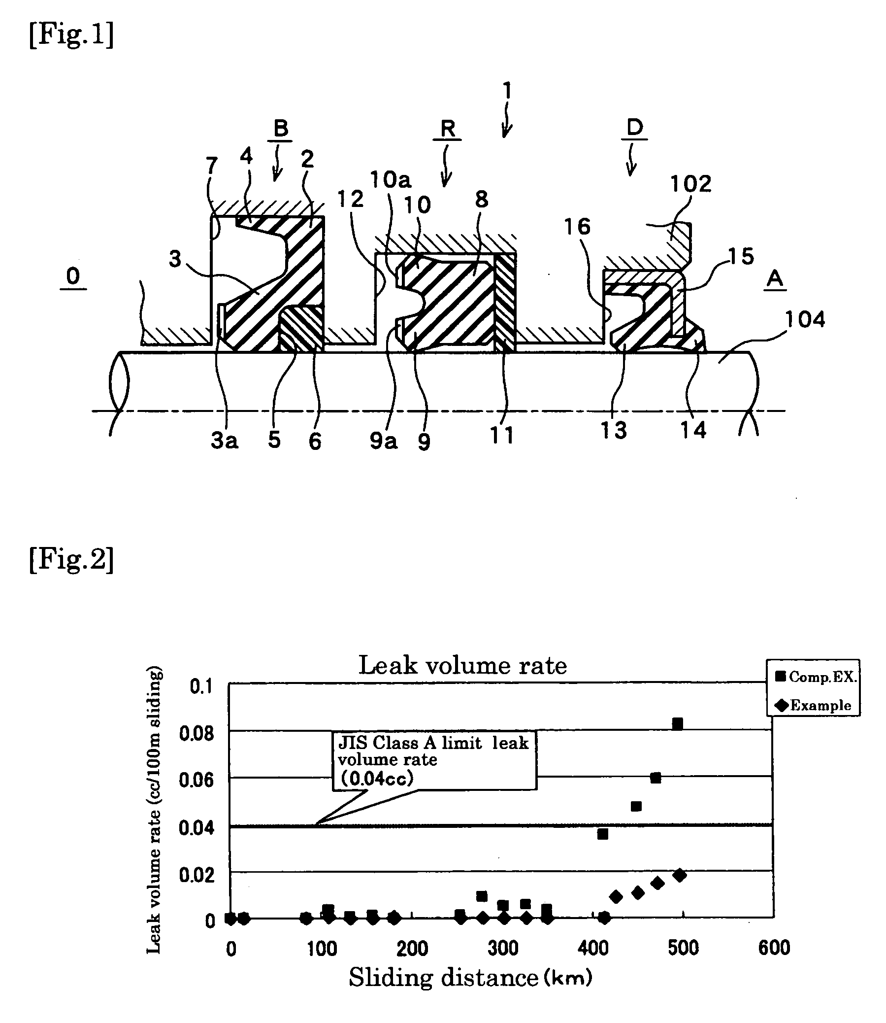
[0079]A rod sealing system, as shown in FIG. 1, was made up, using the heat-treated thermoplastic polyurethane molding product obtained in the afore-mentioned Reference Example, and subjected to a durability test under the following conditions to calculate a rate of loss of resilience as follows:

Rate of loss of resilience (%)=(interference before test−interference after test) / (interference before test)×100

[0080](Durability Test Conditions)

[0081]Pressure: 42 MPa

[0082]Sliding speed: 400 mm / sec.

[0083]Sliding distance: 500 km and 120 km

[0084]Temperature: 110° C. and 120° C.

[0085]In rod sealing system 1 of the working embodiment as used in the afore-mentioned durability test, U-shaped packing 2 of buffer ring B was made of the heat-treated thermoplastic polyurethane molding product obtained in the afore-mentioned Reference Example; backup ring 6 of buffer ring B was made of polyamide (80NP, a product of NOK); U-shaped packing 8 of ro...


PUM

PropertyMeasurementUnit
glass transition point Tgaaaaaaaaaa
temperatureaaaaaaaaaa
temperaturesaaaaaaaaaa

Abstract

In a rod sealing system, which comprises a buffer ring, a rod seal, and a dust seal, provided successively in this order from a fluid hydraulic side toward the outside in an annular clearance between two members in reciprocating motion, the buffer ring is made up of a thermoplastic polyurethane molding product obtained by subjecting a thermoplastic polyurethane molding product prepared by reaction of (A) a high molecular weight polycarbonatediol having a number average molecular weight Mn of 500-6,000, (B) an aromatic diisocyanate, and (C) a low molecular weight diol as a chain elongation agent in an NCO/OH ratio of 0.95-1.20, to heat treatment under conditions that a glass transition point (Tg) of hard phases becomes 170° C. or higher, preferably 170-230° C., and an endothermic peak area (ΔH) at Tg becomes 5 J/g or more, by differential scanning calorimetry. The buffer ring made up of the thermoplastic polyurethane molding product has a distinguished heat resistance capable of withstanding the service environmental temperature, particularly maximum 120° C., compression set characteristics, follow-up to eccentricity, etc.

Description

TECHNICAL FIELD[0001]The present invention relates to a rod sealing system, and more particularly to a rod sealing system, which comprises a buffer ring, a rod seal, and a dust seal, provided successively in this order from a hydraulic fluid side toward the outside in an annular clearance between two members in reciprocating motion.BACKGROUND ART[0002]A rod sealing system, which comprises a buffer ring, a rod seal, and a dust seal, provided successively in this order from a hydraulic fluid side toward the outside in an annular clearance between two members in reciprocating motion is disclosed in the following Patent Literature 1, and shown in FIG. 1 as a half-cutaway cross-sectional view, where a rod sealing system 1 comprises a rod seal R as the main seal for preventing leakage of a working oil to the outside, a buffer ring B provided on the oil hydraulic side O of the rod seal R to buffer the impact pressure or pressure fluctuations at a high-load stages, or to shut off the inflow...

Claims


Application Information

Patent Timeline
Patent Type & Authority Applications(United States)
IPC IPC(8): F16J15/32C08G18/32C08G18/44C08G18/65F15B15/14F16J15/18F16J15/3284
CPCC08G18/10C08G18/44C08G2140/00C09K3/1021C08G18/3206F16J15/20C09K3/10F15B15/14
Inventor MATSUI, NORIYUKIHIRANO, MANABUKUZUMAKI, YOSHIHIROSAITO, KUNIYOSHITAKADA, HAYATO
Owner UNIMATEC CO LTD
Why Eureka
Try Eureka