Optical resonance analysis unit

a technology of optical resonance and optical resonance, applied in the direction of pumping plants, containers, using liquid separation agents, etc., can solve the problems of loss of contrast, “hot spots” or image flare, loss of contrast, etc., to prevent accurate measurement of binding reactions on affected roises, reduce buffer/sample interface mixing, and reduce the effect of flexibility

Inactive Publication Date: 2009-08-27
GE HEALTHCARE BIO SCI CORP
View PDF23 Cites 35 Cited by
  • Summary
  • Abstract
  • Description
  • Claims
  • Application Information

AI Technical Summary

Benefits of technology

[0038]Another advantage of the most preferred fluidics system described herein is the capability for “on the fly” sample loading which is made possible by two separate pumps, one driving the buffer solution and one driving the sample, which allows the user to prepare the sample while the buffer is running through the system. In many instances, it is advantageous using the present instrument, to allow buffer solution to run separately through the system for a few minutes or longer in order to establish a baseline. In addition, in cases where sample loading is time-dependent, for example where the time between sample preparation, mixing, etc., and loading is required to be short due to sensitive samples that may degrade over time and/or with changes in temperature, independent buffer and sample fluidic paths allow samples to be prepared and loaded just minutes or even seconds before injection and introduction onto the sensor. Sample recirculation as described above is also advantageous for samples with particularly slow on-rates (i.e., low association constants) as it allows the samples to keep (re)cycling through the system for sufficient lengths of time to observe sufficient response to calculate accurate association constants kON.
[0039]In addition, if a reaction proceeds slowly, then recirculation is particularly advantageous in that small amounts of sample may be continually recontacted with the sensor surface, whereas if this option were not available, the user would have to acquire much larger amounts of a sample, which may be difficult or prohibitively costly, if not impossible. This “endless supply” of re-circulating sample thus provides sufficient flexibility in both the contact time and flow rate to allow for the monitoring of very slow or mass transport-limited reactions.
[0040]The use of a 4-way valve is particularly advantageous in the fluidics system of the present invention because: (1) it maintains the integrity of the concentrations of the buffer and samples as the system is simultaneously running and preparing for sample injection and, (2) the location of the 4-way valve, i.e., immediately adjacent the sensor, minimizes any mixing of the buffer/sample interface.
[0041]The fluidics system of the present invention also includes a “bubble blast” high velocity pulsating flow driven by a syringe pump. When putting a new flow cell (containing a new sensor chip) into operation, it is commonly the case that air bubbles remain in the cell gap after filling with buffer. Air bubbles may also inadvertently be introduced during sample switching and other fluid transport operations. These bubbles prevent accurate measurements of the binding reactions on affected ROIs and must be removed, which can be difficult, particularly where the dimensions of the flow cell containing the sensor a...

Problems solved by technology

However, current grating coupled SPR methods employing angle scanned array imaging to measure many samples in parallel share certain disadvantages with other angle scanned optical resonance sensor methods, including Kretchmann SPR imaging approaches.
Many of the problems associated with angle scanned array SPR are related to system optics and the fact that SPR array imaging requires a relatively high numerical aperture imaging system to accommodate the range of illumination angles involved in an SPR scan, but for each individual exposure or image frame during an angle scan the light is highly concentrated into a small portion of the full aperture pupil.
Such aberrations are common in conventional high numerical aperture imaging systems but are generally tolerated, merely causing loss of contrast or resolution when all aperture angles are present simultaneously.
However, in array SPR they pose a serious problem since highly accurate reflectance measurements must be made at carefully defined locations on the sensor chip surface as a function of illumination angle.
However, such post-event data processing compensation for the walking effect is a less preferable solution to the generation of more accurate data in the first place.
Another problem associated with the aforementioned severe instantaneous underfilling of the aperture pupil in current SPR array instruments is the phenomenon of “hot spots” or image flare caused by multiple reflections between the various optical surfaces, particu...

Method used


Image

  • Optical resonance analysis unit
  • Optical resonance analysis unit
  • Optical resonance analysis unit

Examples


Embodiment Construction

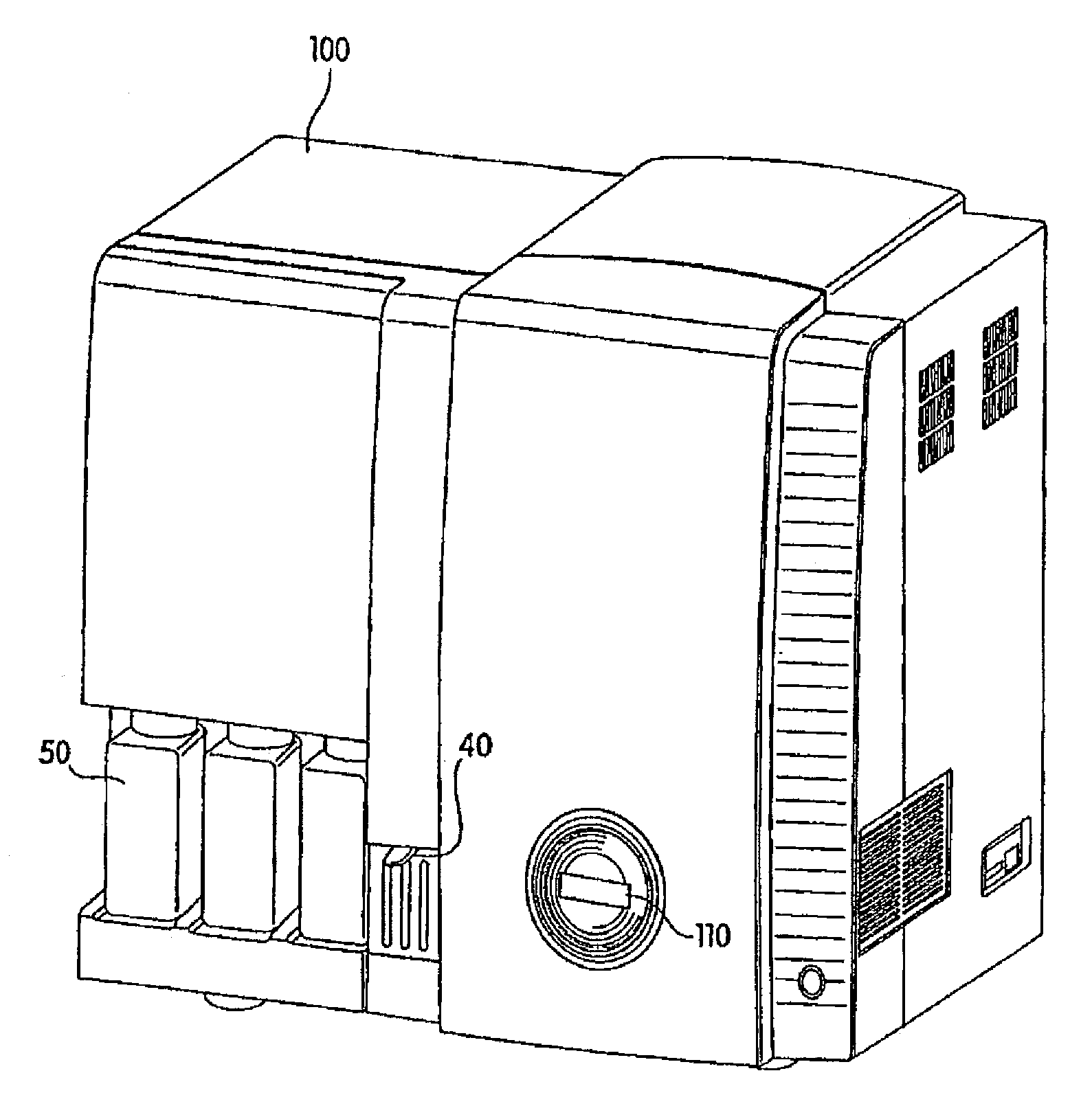
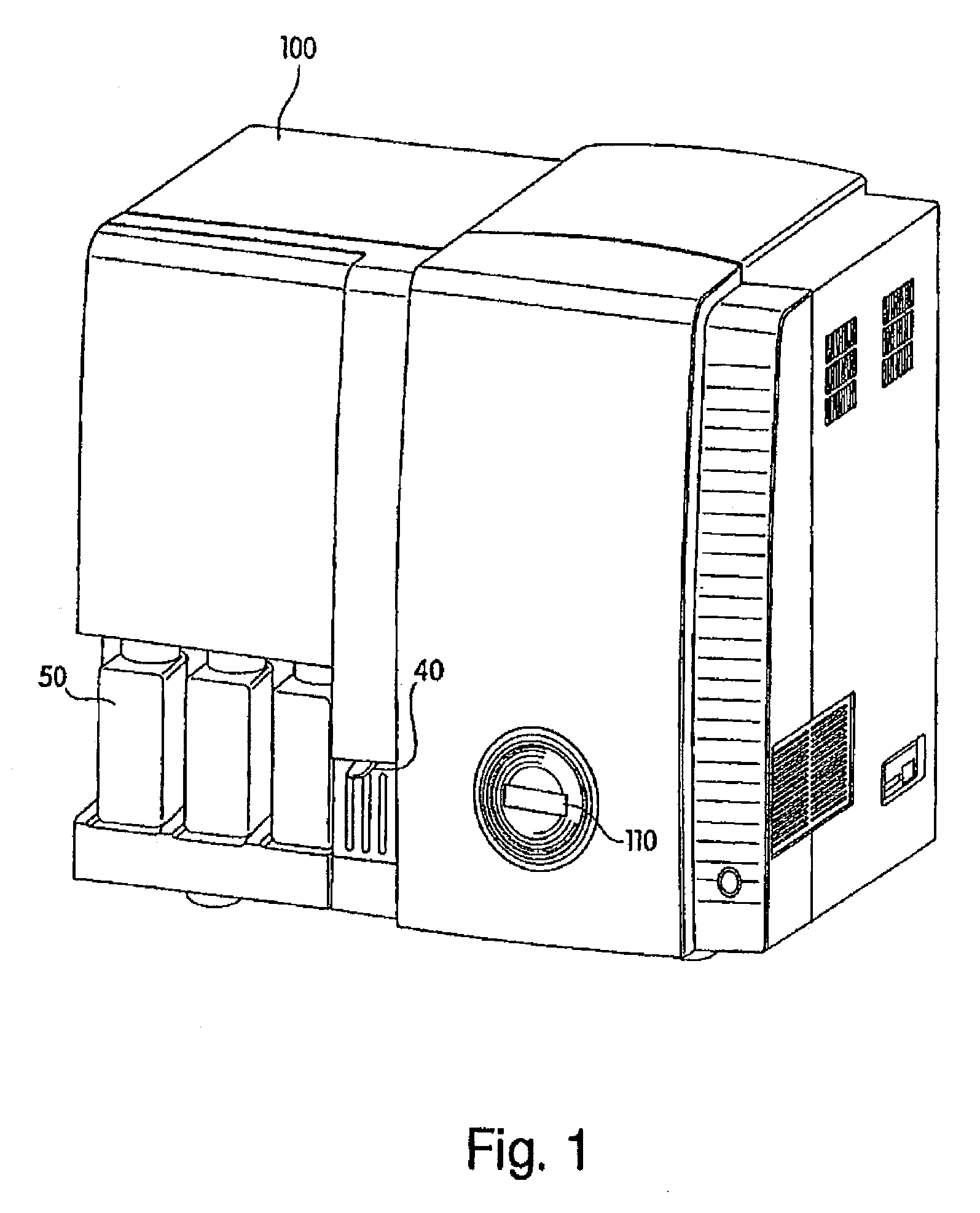
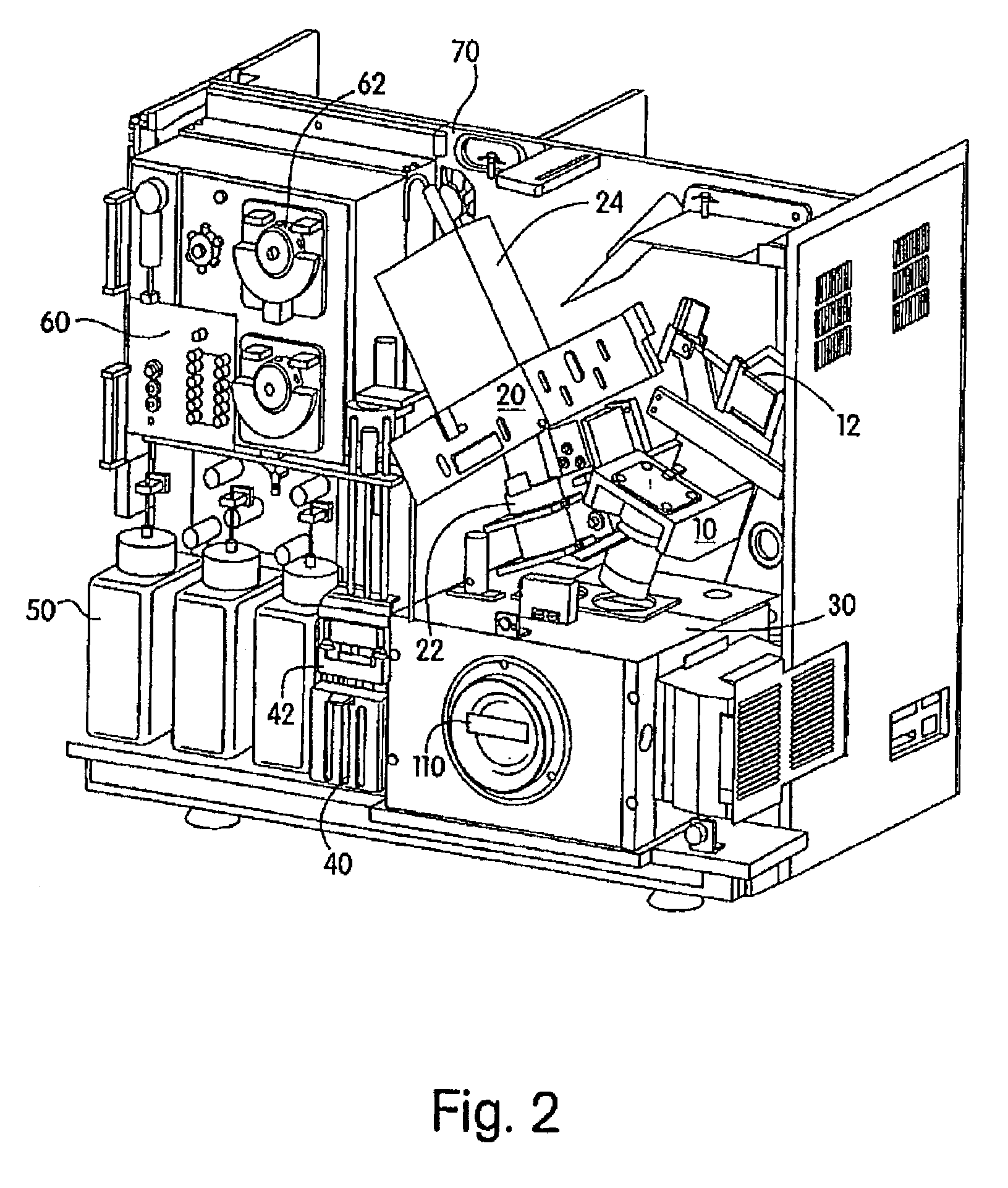
[0057]The present invention is directed to an improved optical resonance analysis instrument for use especially in surface plasmon resonance (SPR) capable of simultaneous measurement of an array of reaction sites. The array SPR instrument may be any type comprising a two dimensional reflective SPR sensor array and a detector assembly oriented to receive the reflected image of the SPR sensor array, such as an array type grating coupled SPR instrument, an array type prism coupled SPR instrument, or the like. In the following description a detailed embodiment of an array type grating coupled SPR instrument is presented, but it should be noted that essentially all features may be directly applicable on other types of array SPR instruments, as is briefly disclosed for an array type prism coupled SPR instrument with reference to FIG. 10. In particular, the present invention combines a number of features which, in addition to enabling real-time analysis of up to thousands of molecular bind...


PUM

PropertyMeasurementUnit
Angleaaaaaaaaaa
Temperatureaaaaaaaaaa
Angleaaaaaaaaaa

Abstract

An array surface plasmon resonance (SPR) analysis instrument comprising a reflective SPR sensor array, a light source assembly arranged to project a collimated beam of light onto the reflective SPR sensor array to provide a reflected array image of the sensor array, and to scan the incident angle of the collimated beam of light over an angular range, and a detector assembly oriented to receive the reflected array image of the sensor array over the angular range, the detector assembly comprises a two-dimensional detector sensing element that is tilted with respect to the optical axis of the lens assembly in accordance with the Scheimpflug condition, and a lens assembly for focusing the reflected array image of said SPR sensor array onto said tilted detector sensing element. The lens assembly comprises an objective section which is arranged to produce a virtual image of the tilted reflected array at infinity, followed by an imaging section arranged to transform the virtual image of the tilted reflected array into a real tilted image on the tilted detector sensing element.

Description

CROSS-REFERENCE TO RELATED APPLICATIONS[0001]This application is a continuation-in-part of U.S. patent application Ser. No. 10 / 566,303, filed Jan. 27, 2006, now abandoned, which is a filing under 35 U.S.C. § 371 and claims priority to international patent application number PCT / US2004 / 024789 filed Aug. 2, 2004, published on Feb. 10, 2005, as WO 2005 / 012878, and claims priority to U.S. provisional patent application Nos. 60 / 492,061 and 60 / 492,062 both filed Aug. 1, 2003; the disclosures of which are incorporated herein by reference in their entireties.FIELD OF THE INVENTION[0002]This invention relates generally to optical resonance analysis systems. Specifically, the invention relates to an improved instrument for conducting grating coupled surface plasmon resonance imaging utilizing illumination and detection systems for the real-time analysis of multiple reactions taking place on the surface of a sensor array.BACKGROUND OF THE INVENTION[0003]The basic principle of operation of grat...

Claims


Application Information

Patent Timeline
IPC IPC(8): G01N21/55
CPCG01N21/253G01N21/7743G01N21/553Y10T137/86035
Inventor TRACY, DAVID H.BROCKMAN, JENNIFER M.FERRARA, KEITH S.SHENKER, MARTINKERSTEN, ROBERTCOHEN, STEVEN E.BODLEY, GARYTUXBURY, PATRICKHETHERINGTON, PAULPICOZZA, ENRICO
Owner GE HEALTHCARE BIO SCI CORP
Why Eureka
Try Eureka