Piston ring with chromium nitride coating for internal combustion engines

a technology of chromium nitride and internal combustion engine, which is applied in the direction of braking system, natural mineral layered products, instruments, etc., can solve the problems of engine liners scratching, internal fragility, surface damage, etc., and achieve the effect of superior resistance to the initiation of micro-cracks

Active Publication Date: 2009-11-12
MAHLE INT GMBH +1
View PDF11 Cites 38 Cited by
  • Summary
  • Abstract
  • Description
  • Claims
  • Application Information

AI Technical Summary

Benefits of technology

[0015]It is an object of the present invention to provide a piston ring with a coating of chromium nitride with columnar crystal structure of CrN obtained by a process of physical vapo...

Problems solved by technology

However, in some recent engines extremely high loaded or in engines with a high level of combustion pressure, as the ones designed for the next decade, this ceramic coating of chromium nitride presents a intrinsic fragility which takes to the appearance of micro-cracks on its surface.
These micro-cracks propagate and their connection takes to a loss of small pieces of the coating, generating damages on its surface and, in some cases, scratches on the engine liners.
Not only the scratches but also the damages are usually considered functional failure of the piston rings.
Besides, this ...

Method used


Image

  • Piston ring with chromium nitride coating for internal combustion engines
  • Piston ring with chromium nitride coating for internal combustion engines
  • Piston ring with chromium nitride coating for internal combustion engines

Examples


example 1

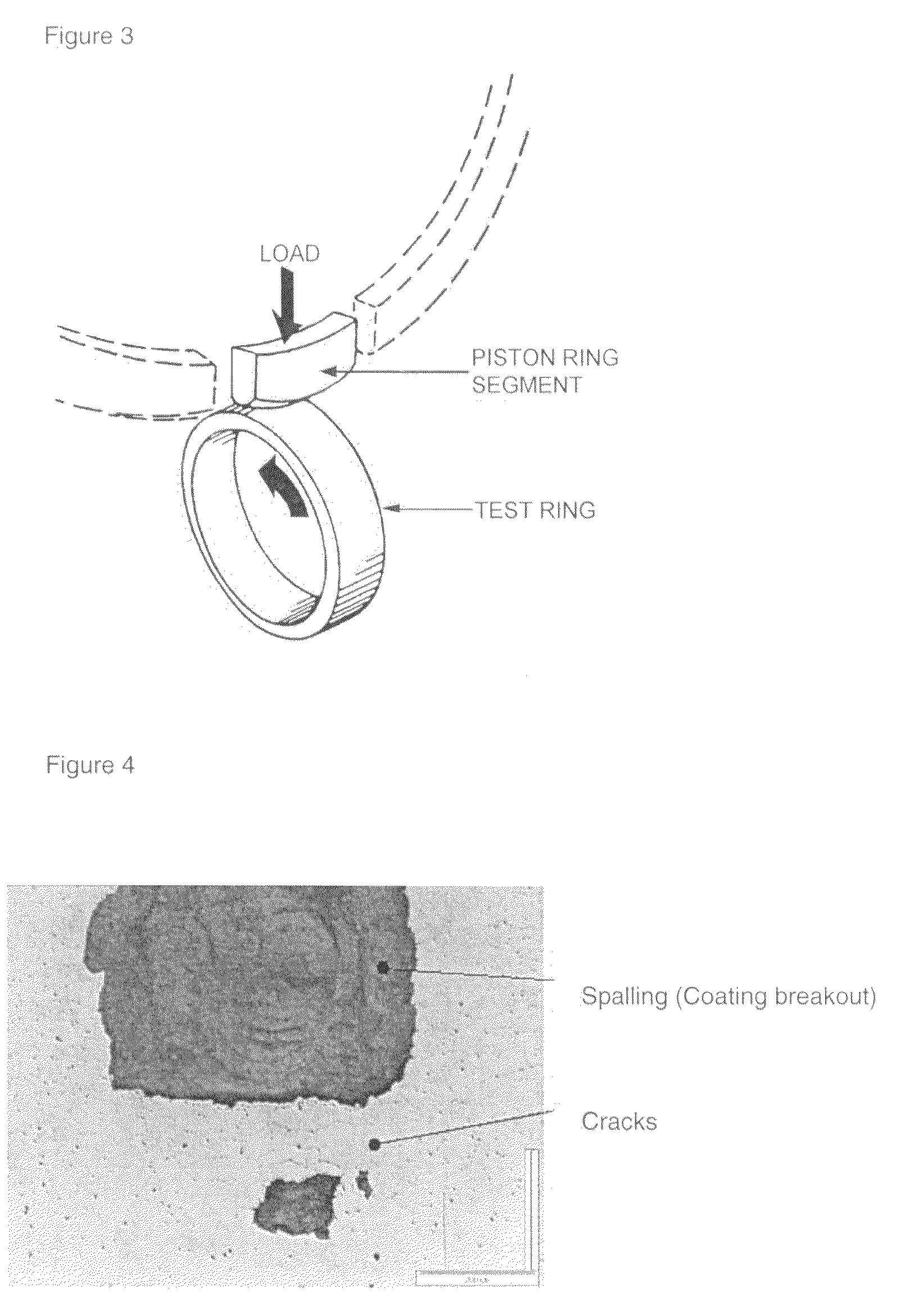
[0052]With the above-mentioned method, piston rings were produced represented by sample coating 4 on Table 1. Three rings of this condition were assembled in a heavy duty Diesel engine (6 cylinders 450 kW). The rings were submitted to an accelerated thermal shock test in a dynamometer cell for 500 hours, where the liner and block thermal deformation conditions, besides severe conditions regarding oil film rupture, are particularly keen to the generation of high load on the coated surface of the piston rings. Visual and metallurgical evaluation of the rings after the test was conducted and can be seen on Table 2, test 1.

[0053]Table 2 also indicates the assembling configuration of the compression rings in the six cylinders of the engine. The cylinder liners as well as the second ring and the oil ring were taken from the same production lots to minimize as much as possible the variables involved.

[0054]The rings of coating sample 1 in Table 1 represent the state of the art, and they hav...

example 2

[0057]With the above-mentioned method, piston rings were produced represented by sample coatings 5 and 6 on Table 1. Two rings of each condition were assembled in a 6 cylinders 400 kW heavy duty Diesel engine. The rings were submitted to an accelerated thermal shock test in a dynamometer cell for 500 hours, in conditions identical to example 1. Visual and metallurgical evaluation of the rings after the test was conducted and can be seen on Table 2, test 2.

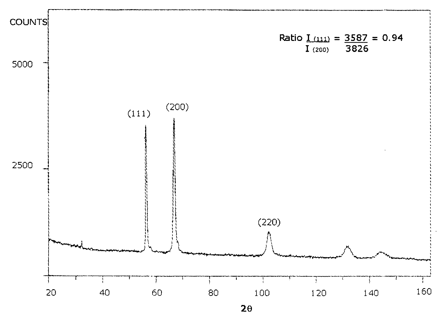
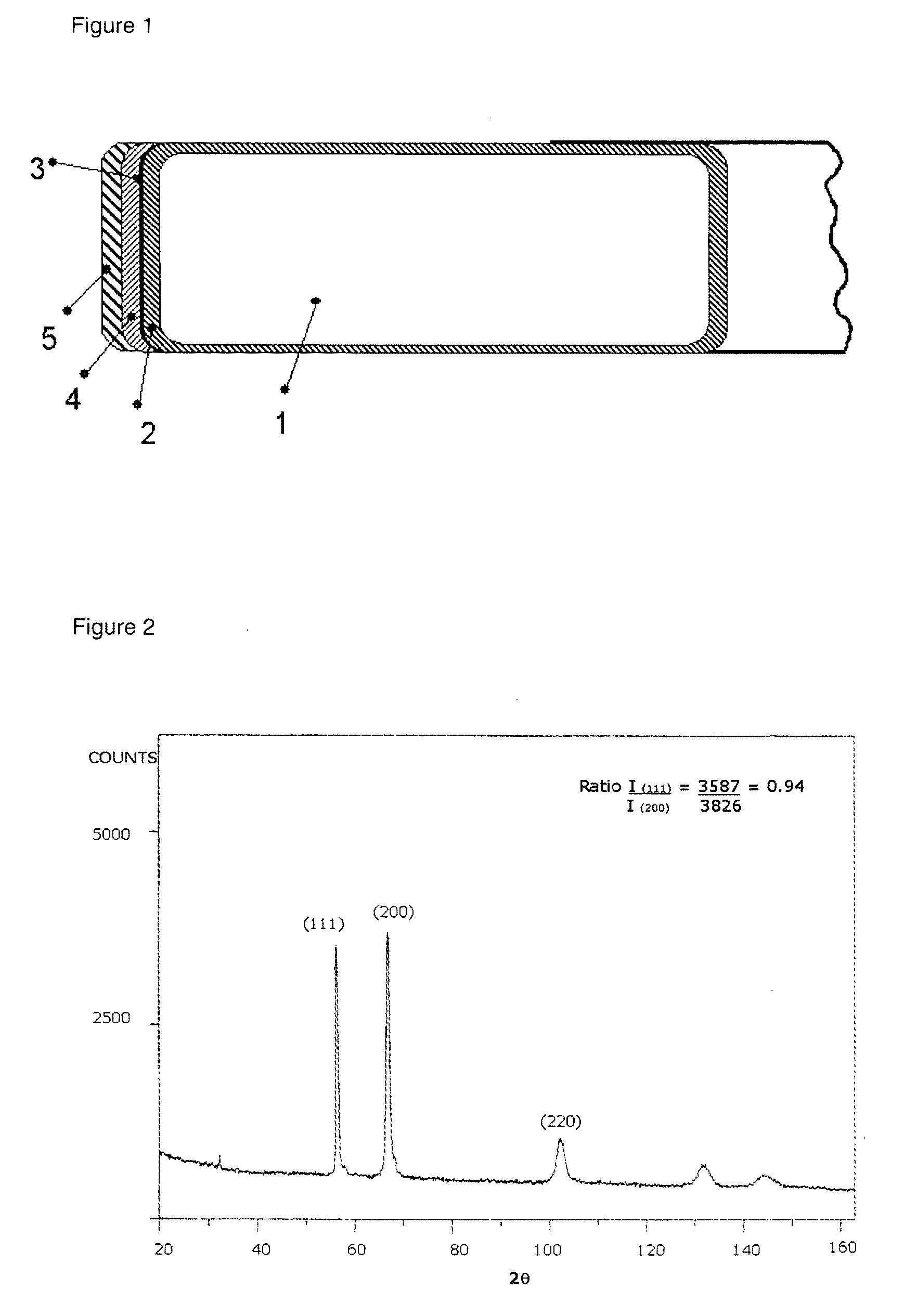
TABLE 2Visual and metallurgical evaluation of rings after engine testEngine TestAssembling positionOxygen contentRatiocrackSamplesTest 1Test 2(%)(111) / (200)after testPrior art1cylinder #1, #3 and #6—0.30.25yesComparative3—cylinder #1 and #310.40.13yesExamplesEmbodiments4cylinders #2, #4 and #5—1.20.85no5—cylinders #4 and #51.31.03no6—cylinders #2 and #62.30.98no

[0058]Table 2 also indicates the assembling configuration of the compression rings in the six cylinders of the engine. The cylinder liners as well as the second rings and th...


PUM

PropertyMeasurementUnit
Fractionaaaaaaaaaa
Fractionaaaaaaaaaa
Thicknessaaaaaaaaaa

Abstract

The invention relates to a piston ring for internal combustion engines, the piston ring comprises a steel or cast iron base material with a coating of chromium nitride deposited by a physical vapor deposition process on a sliding surface of the piston ring, wherein the coating is composed of a columnar crystal structure of CrN with the following features:
    • (a) an oxygen content in solid solution of 0.5 to 2.5 wt %;
    • (b) a content of uniformly dispersed micro-pores of less than 10% in volume of the coating; and
    • (c) an X-ray diffraction intensity ratio of (111) planes to (200) planes parallel to the surface in the range of 0.80 to 1.20.

Description

BACKGROUND OF THE INVENTION[0001]1. Technical Field of the Invention[0002]The present invention relates to a piston ring for internal combustion engines, comprising a steel or cast iron base material; and a coating of chromium nitride deposited by a physical vapor deposition process on a sliding surface of the piston ring.[0003]2. Description of the Related Art[0004]The use of a chromium nitride film with typical crystal structure of CrN phase on the outer peripheral surface of a piston ring provides high wear resistance for this component. This film is widely used in modern engines, last developments, with high mechanical and thermal loads. Such coating is obtained by physical metallic vapor deposition usually generated by a source of cathodic arc.[0005]However, in some recent engines extremely high loaded or in engines with a high level of combustion pressure, as the ones designed for the next decade, this ceramic coating of chromium nitride presents a intrinsic fragility which ta...

Claims


Application Information

Patent Timeline
IPC IPC(8): F16J9/26C23C14/34
CPCC23C14/0036Y10T428/265F16J9/26C23C14/0641
Inventor ARAUJO, JULIANO AVELARMARQUES, GISELA ABLASSARABANDA, JOSE VALENTIM LIMABANFIELD, ROBERT RICHARD
Owner MAHLE INT GMBH
Why Eureka
Try Eureka