Discharge plasma reactor

a discharge reactor and dielectric barrier technology, applied in the field of single or dual dielectric barrier discharge reactors, can solve the problems of high frequency, expensive alternating current voltage, and only successful generation of known glow discharge plasmas, and achieve the effect of improving surface coating adhesion and high efficiency

Inactive Publication Date: 2009-12-03
EON LABS
View PDF16 Cites 28 Cited by
  • Summary
  • Abstract
  • Description
  • Claims
  • Application Information

AI Technical Summary

Benefits of technology

[0006]In use, the inductively-coupled pulsed DC high pressure plasmas generated by the apparatus and method of the present invention may be useful in many different industries and applications. For example, potential lighting applications include, but are not limited to: thin flat panel combination with a suitable Phosphor and gas for white light source for general lighting; thin flat panel combination with a suitable Phosphor and gas for high intensity, low temperature white light source (replace halogen lamps); thin flat panel in combination with a suitable Phosphor and gas for multi-colored light sources for signage; thin panel backlighting for LCD displays; transparent flat panel lighting fixtures (Windows that turn on to provide light); efficient, low temperature and controllable UV light source for the tanning industry; and, in conjunction with a suitable gas or metal vapor for efficient street lighting.
[0007]Potential sound transducer applications include high efficiency, wide dynamic response plasma tweeters and, in combination with the proper drive electronics, to create an audible and ultrasound transducer for frequencies from 2-18,000,000 Hz. Surface treatment applications include: anodization of metals (Al, Si, Ti, Cu), etc for passivation or electrical isolation; nitriding of surfaces for passivation or hardening; SiN, TiN, etc; and removal of residual hydrocarbons or adsorbed water vapor for improved adhesion of surface coatings. Chemical processing applications include: the reactor of the present invention in conjunction with suitable process controls and feed gas for creation of monatomic gasses including hydrogen, nitrogen and oxygen; the reactor of the present invention in conjunction with suitable process controls and feed gas for creation or destruction of Ammonia; the reactor of the present invention in conjunction with suitable process controls and feed gas for creation or destruction of Hydrogen Peroxide; efficient safety burn-off protection for combustible gases (plasma pilot light); the reactor of the present invention in conjunction with suitable feed gas for destruction of hazardous effluents from central station coal fired power plants, chemical processing plants, industrial incinerators; the generation of ozone in water or air. Potential germicidal / sanitation applications include: destroying mold, bacteria and viruses on surfaces; destroying mold, bacteria and viruses in gases (Plasma filter); and destroying mold, bacteria or viruses in liquids (Water purification). The dielectric electrodes and inductive coupling of the present invention allow the plasma cell to operate while submerged in water or other suitable liquid.
[0009]Automotive applications include: creation or destruction of nitrous oxides (NOx); long life, fast and efficient ignition source (Plasma Spark Plugs); reduction of un-burned hydrocarbons in automotive exhaust (Replace catalytic converter); high intensity head lights—similar to halogen lamps but more efficient and lower temperature for longer life. Other industrial applications include: operation in inter-dielectric arc mode and at high power for welding or cutting sheet metal; operation in inter-dielectric arc mode and at high power for deposition of metal or ceramic coatings; polymer treatment; waste remediation; textiles; replaces deep liquid penetration with surface reactions (reduce flammability); improved pigment fixation (color dyeing). Medicinal. (Biocompatibility) uses include: biomedical; airborne decontamination; and device sterilization.

Problems solved by technology

However, known glow discharge plasmas have traditionally only been successfully generated in typically low pressure or partial vacuum environments that necessitate batch processing and the use of expensive vacuum systems.
However, only when these conventional DBDs were powered by high frequency AC power supplies was a glow discharge mode available.
There are other drawbacks in traditional DBD plasma generation, such as the requirement for high frequency (normally in the RF range), expensive alternating current voltage and complex, impedence matching circuitry.

Method used


Image

  • Discharge plasma reactor
  • Discharge plasma reactor
  • Discharge plasma reactor

Examples


Embodiment Construction

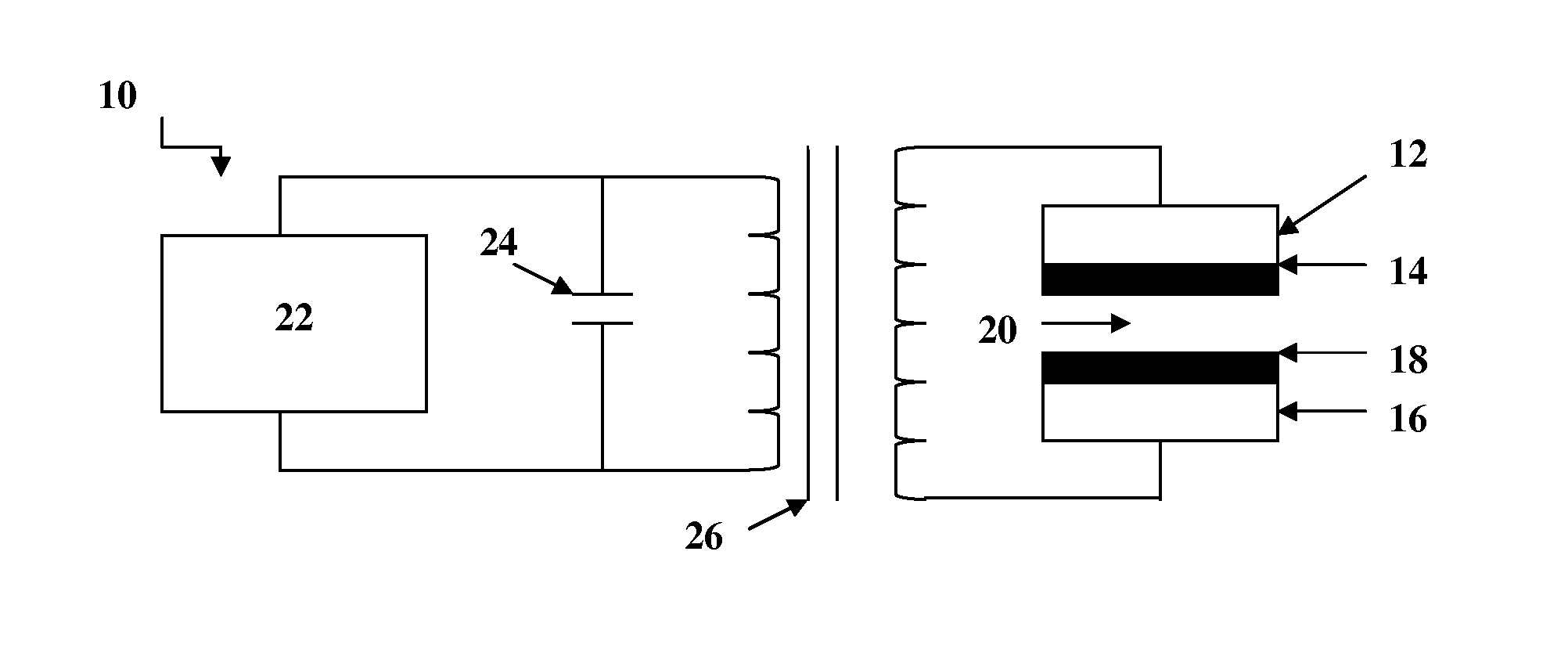
[0017]A dielectric barrier discharge reactor 10 embodying various features of the invention is shown in the drawings. Reactor 10 may be housed in a chamber (not shown) capable of controlling temperature, pressure, gas, and / or gas flows into and out of the chamber. In certain desirable applications such as lighting, sound generation, and power generation, a sealed chamber may be desirable. However, for molecular separation and recombination applications, an open system with reactor 10 substantially directly in the path of a high pressure gas flow may be more desirable. In the following embodiments of the present invention, reactor 10 is used to initiate glow discharge plasma at atmospheric pressure, but it is within the scope of the present invention to utilize reactor 10 in any desired atmospheric pressure depending upon the desired application thereof.

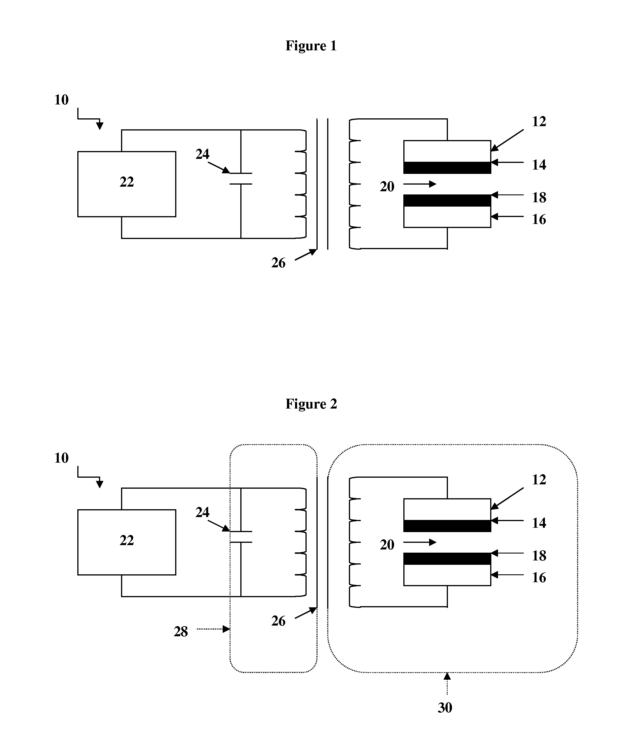
[0018]As shown in FIG. 1, one embodiment of reactor 10 generally includes at least one first electrode 12, a first dielectric layer ...


PUM


Abstract

The present invention is generally directed to a single or dual dielectric barrier discharge reactor for generating flow discharge plasmas at atmospheric pressure or higher pressures. In particular, the present invention relates to a providing stable, energy efficient, glow discharge plasmas having a controlled discharge gap.

Description

BACKGROUND OF THE INVENTION[0001]This invention relates generally to a single or dual dielectric barrier discharge reactor for generating glow discharge plasmas at low to high pressures including atmospheric pressure or higher pressures. In particular, the present invention relates to a providing stable, energy efficient, glow discharge plasmas having a controlled discharge gap.[0002]The term “plasma” is generally used to describe fully or partially ionized gases containing many interacting free electrons, ionized atoms or molecules and free radicals. Plasma has many useful applications including, but not limited to, lighting, sound generation, molecular disassociation, surface modification of polymers, cleaning, etching and thin film deposition. This state of matter may be produced by the action of either very high temperatures or strong electric fields whether constant direct current (DC) or time varying radio frequency (RF) or microwave electromagnetic fields. High temperature or...

Claims


Application Information

Patent Timeline
Patent Type & Authority Applications(United States)
IPC IPC(8): B01J19/08
CPCH05H1/24H05H1/2406
Inventor BUCHANAN, WALTER R.HRUSKA, CHRISTOPHER D.
Owner EON LABS
Why Eureka
Try Eureka