Manufacturing process for chalcogenide glasses

Inactive Publication Date: 2010-01-28
THE UNITED STATES OF AMERICA AS REPRESENTED BY THE SECRETARY OF THE NAVY
View PDF7 Cites 16 Cited by
  • Summary
  • Abstract
  • Description
  • Claims
  • Application Information

AI Technical Summary

Benefits of technology

[0014]The chalcogenide glasses of the present invention offer many benefits in at least some embodiments of the invention. Slow cooling the glass melts minimizes stresses during quenching. Moreover, controlled slow cooling may enable thermal equilibrium and steady state to occur in the glass melt. This contributes to a lower energy and stable state of the glass melt just before quenching. This also results in a small meniscus and, therefore, higher yield. The yield of useable glass is typically greater than 80%, compared with typically less than 60% for the conventional method. Additionally, vertical homogenization of the melt may eliminate or reduce the refractive index perturbations. The glass potentially can be used to make high optical quality fiber at potentially reduced cost, and fibers made using the glass of the present invention may be less susceptible to refractive index perturbations. Therefore, cost may be reduced and fibers made from the glasses of the pres

Problems solved by technology

The problem is that when the ampoule is set from a 45 degree angle to a 90 degree angle, the top of the glass melt near the meniscus undergoes turbulent viscous flow.
When the ampoule is quenched in water, that unstable and viscous state near the top of the glass melt is frozen in place.
This leads to the typical refractive index perturbations observed in these glasses.
This conventional quenching process leads to a large meniscus and, therefore, lower yield of useable glass.
From a commercial perspective, this increases the cost of the glass.
During submersion in water, the melt quenches rapidly and leads to rapid pull away of the glass all at once from the quartz, leading to a powerful shock wave which causes cracking of the chalcogenide glass.
This can be manifested as micro-cracking in the glass or can sometimes lead to catastrophic failure of the glass.
This probl

Method used


Image

  • Manufacturing process for chalcogenide glasses
  • Manufacturing process for chalcogenide glasses
  • Manufacturing process for chalcogenide glasses

Examples


example 1

Example of Material Involving Stable Chalcogenide Glasses

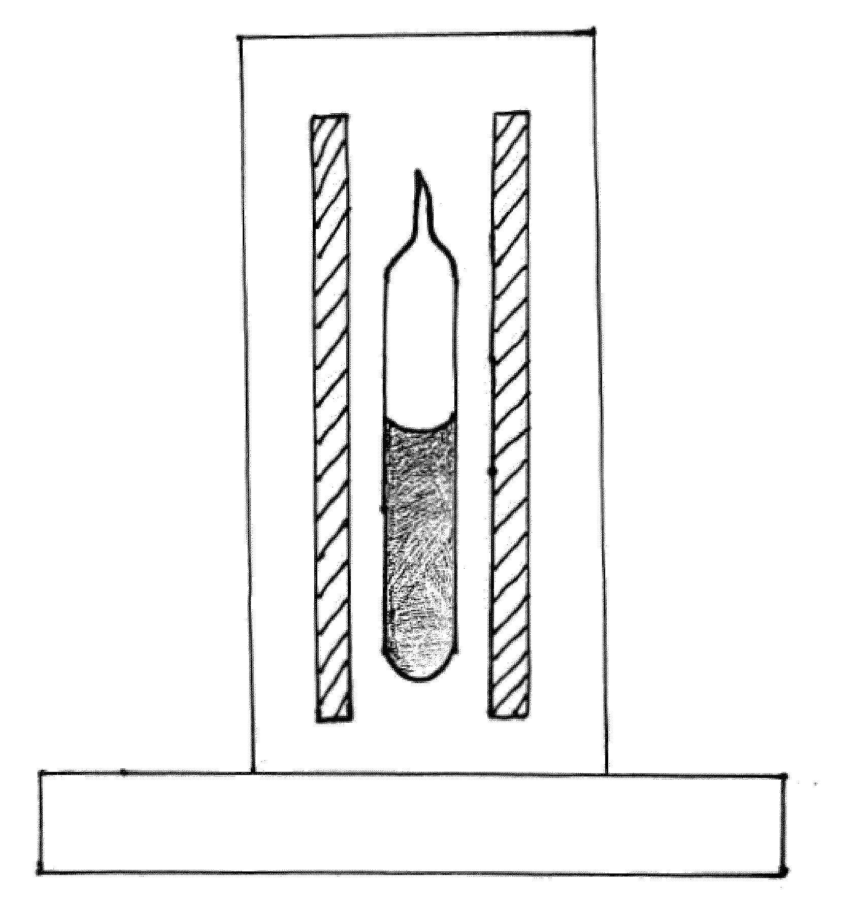
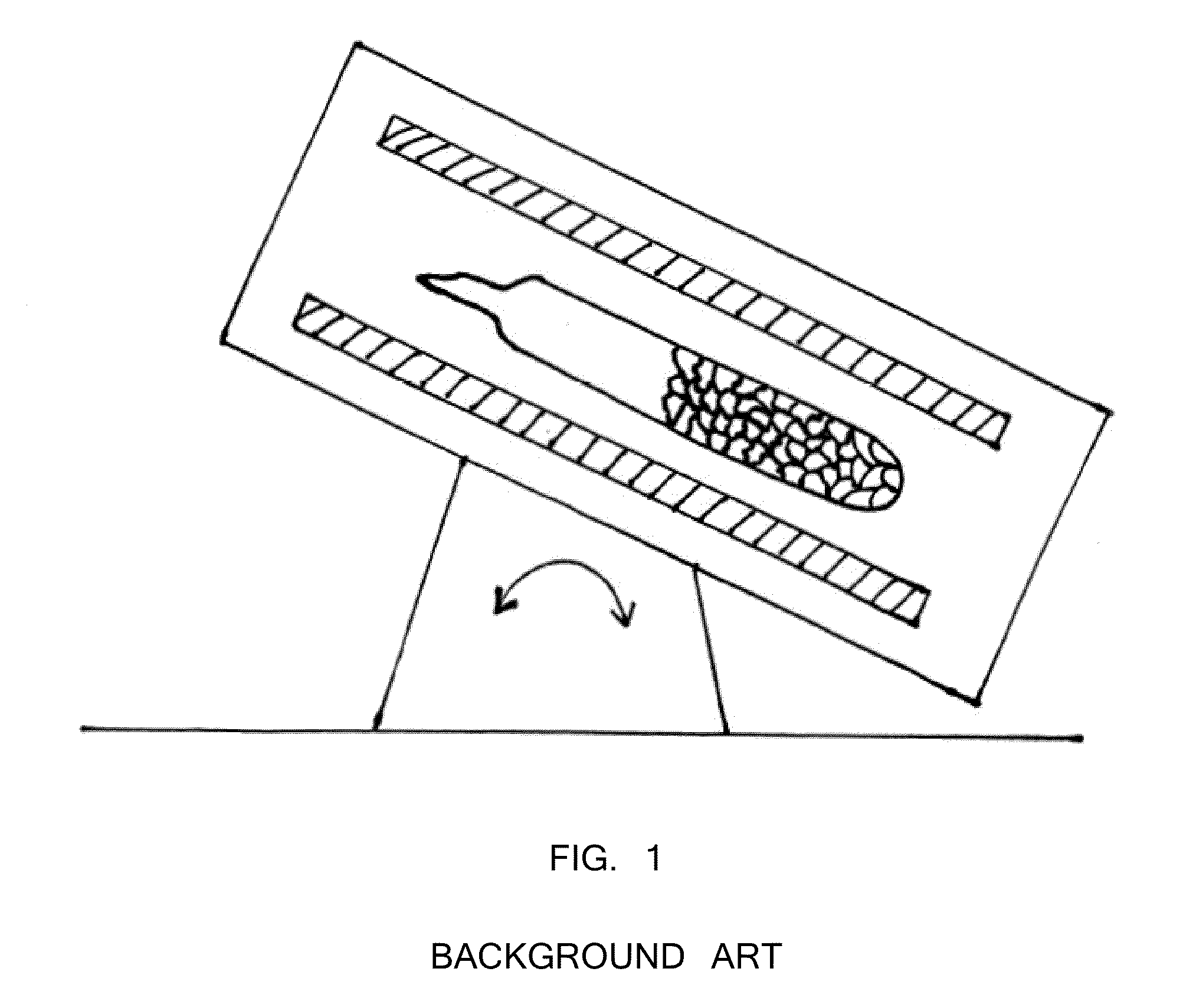
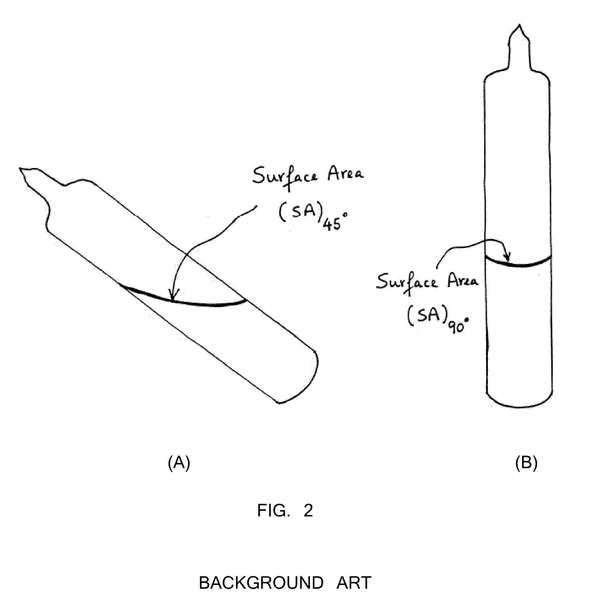
[0041]First, 47.92 grams of arsenic and 32.08 grams of sulfur precursors (a total of 80 grams) were batched in a silica ampoule with a composition of As39S61. The ampoule was evacuated for 4 hours at 1×10⁻⁵ Torr. The ampoule was sealed using a methane / oxygen torch. Inside a rocking furnace with a 45 degree angle inclination, the ampoule containing the arsenic and sulfur precursors was melted at 450° C. for 4 hours. For homogenization mixing and uniform glass melting, the temperature was increased to 600° C. for 4 hours and 800° C. for 10 hours. Next, the rocking furnace was set at a 45 degree inclination and the temperature was lowered to 700° C. for 1 hour. The ampoule was transferred from the 45 degree furnace into another vertically 90° furnace with the temperature set at 700° C. (FIG. 4). The temperature of the vertical furnace was set at 700° C. for 1 hour for homogenization and uniform mixing. Next, the temperature of th...

example 2

Example of Material Involving Rare-Earth Doped Chalcogenide Glasses

[0048]Oxide impurities present in the starting components (germanium, arsenic, and selenium) were removed by melting the precursors with the addition of 10 ppm of aluminum, zirconium, magnesium, or any combination thereof. First, 14.905 grams of germanium, 13.631 grams of arsenic, 51.102 grams of selenium, and 0.008 grams of aluminum precursors (approximately 79.646 grams) were batched in a silica ampoule in chamber A (FIG. 6). Table 2 shows the typical batch size to make about 80 grams of core cullet. The ampoule was evacuated for 4 hours at 1×10⁻⁵ Torr. The ampoule was sealed using a methane / oxygen torch.

TABLE 2Batch calculations for making ~80 grams of core cullet rare-earthdoped glass rod with Ge19.75As17.5Ga0.5Se62.25 composition80 gMol %Mol. Wt.batchGe19.75072.5914.905As17.50074.92213.631Ga0.50069.720.362Se62.25078.9651.102100.000~80.000

[0049]The ampoule (chamber A) was placed in the first zone of a two-zone fu...

example 3

Example of Material Involving Unstable Undoped Chalcogenide Glasses

[0055]Optical fiber cladding material for unstable rare-earth doped chalcogenide glasses are often made using unstable undoped chalcogenide glasses. The unstable glasses require a similar technique for purification and cooling. The oxide removal process is similar to the oxide removal step used for making the rare-earth doped core material discussed in Example 2 above. The oxide impurities present in the starting components (germanium, arsenic and selenium) are removed by melting the precursors with the addition of 10 ppm of aluminum. First, 14.935 grams of germanium, 14.230 grams of arsenic, 49.989 grams of selenium, and 0.008 grams of aluminum precursors (approximately 79.162 grams) were batched in a silica ampoule. Table 6 shows the typical batch size to make a 79.162 gram clad cullet. The ampoule was evacuated for 4 hours at 1×10⁻⁵ Torr. The ampoule was sealed using a methane / oxygen torch.

TABLE 6Batch calculation...


PUM

PropertyMeasurementUnit
Temperatureaaaaaaaaaa
Glass transition temperatureaaaaaaaaaa
Liquidus temperatureaaaaaaaaaa

Abstract

The present invention is generally directed to a method of making chalcogenide glasses including holding the melt in a vertical furnace to promote homogenization and mixing; slow cooling the melt at less than 10° C. per minute; and sequentially quenching the melt from the top down in a controlled manner. Additionally, the present invention provides for the materials produced by such method. The present invention is also directed to a process for removing oxygen and hydrogen impurities from chalcogenide glass components using dynamic distillation.

Description

BACKGROUND OF THE INVENTION[0001]1. Field of the Invention[0002]The present invention is generally directed to a method of making chalcogenide glasses, including rare-earth doped chalcogenide glasses, and the materials produced by such method.[0003]2. Description of the Prior Art[0004]To date, the typical way to melt a chalcogenide glass is to heat the elemental precursors in an evacuated and sealed quartz ampoule. The furnace is a rocking furnace which assists in mixing of the melt (FIG. 1). After several hours of rocking at elevated temperature, the furnace is placed at an angle of about 45 degrees and the ampoule containing the melt is pulled out, held vertical for several seconds (FIG. 2), then immersed in water to quench the melt. The problem is that when the ampoule is set from a 45 degree angle to a 90 degree angle, the top of the glass melt near the meniscus undergoes turbulent viscous flow. The glass melt surface area of the 45 degree angle (SA)45 is estimated to be more th...

Claims


Application Information

Patent Timeline
IPC IPC(8): C03C3/32C03B37/075
CPCC03B5/06C03B2201/86C03C3/32Y02P40/57C03B5/2252C03B2211/00
Inventor NGUYEN, VINH Q.SANGHERA, JASBINDER S.BAYYA, SHYAM S.CHIN, GEOFFAGGARWAL, ISHWAR D.
Owner THE UNITED STATES OF AMERICA AS REPRESENTED BY THE SECRETARY OF THE NAVY
Why Eureka
Try Eureka