Compressible fluid pumping system

a compression fluid and pumping system technology, applied in the direction of positive displacement liquid engine, separation process, instruments, etc., can solve the problems of variable leakage back to the low pressure side, magnetic coupling with lower torque limit, reciprocating pump can only emulate continuous rotary pump approximately, etc., to achieve low compressibility, low noise, and low cost

Active Publication Date: 2010-02-18
AGILENT TECH INC
View PDF3 Cites 71 Cited by
  • Summary
  • Abstract
  • Description
  • Claims
  • Application Information

AI Technical Summary

Benefits of technology

[0034]The preferred and alternative embodiments of the present invention represent an improved technique of dynamically compensating for the compressibility of fluids in real time and over large pressure ranges. This improvement results from separation of the function of performing thermodynamic work on a working fluid during compression from the function of accurate metering of the fluid by using separate pumping stages. Pumps are preferably connected in series but other configurations are possible such as a parallel configuration of multiple metering pumps that are fed by a single booster bump. The primary, booster pump operates in a pressure-controlled mode to bring the working fluid near to the secondary pump output pressure. Excess heat generated by this compression step may be transferred from the working fluid in the transfer region between the two pump stages. This allows the embodiments to bring the fluid to a well defined physical state prior to entering the secondary pump stage. The secondary pump is operated in a high precision metering mode and receives the pre-compressed and thermally conditioned fluid. Since the difference between input and output pressure for the secondary pump is quite small despite a high absolute output pressure, the working fluid has very low compressibility in this pumping stage. As a result, the metering function is very accurate with minimal thermal rise, density change or flow / pressure noise even in the absence of compressibility compensation. The technique brings even the most compressible fluids into a range which can be handled by inexpensive, conventional metering pump designs adjusted only to contain the higher absolute pressures.
[0035]Application of the embodiments of this invention can provide precisely metered volumetric flow at high pressure with very low pulsation. Several specific target applications include pumping of liquids in ultrahigh performance chromatographic systems and pumping of liquefied gasses such as CO2 in SFC systems. Moreover, by separating the compression and metering functions, the metering step occurs over a very small range of pressure and temperature. As a result, by measuring pressure and temperature of the metering step to determine fluid density and adjusting volumetric flow accordingly, true mass flow control of the pump can be obtained. Finally, the invention facilitates applications of continuous pump designs such as gear and lobe pumps that offer superior pulse free delivery to reciprocating pumps but have limited ability to generate high differential pressures under the required conditions of purity.

Problems solved by technology

Significant wear of the gears 3, 3′, especially at high pressure and temperature results in variable leakage back to the low pressure side.
Magnetic coupling has lower torque limits than direct drive, however, so gear pumps are generally available only to less than 30 to 50 bar differential pressure.
However, since the very nature of the movement involves stopping and restarting in opposing motions, reciprocating pumps can only emulate continuous rotary pumps approximately.
During compression, volume is systematically decreased and thermodynamic work is performed on the fluid and it tends to heat up.
Heat generated in the fluid is generally a source of inefficiency since it delivers the gas at a considerably lower density than desired.
It is nearly impossible for a robust pump head design to leave no residual fluid at the end of the delivery stroke.
Too close machining tolerances can cause a greater rate of wear and early failure of sealing surfaces. FIG. 4 shows the residual volume of gas remaining at the end of the piston stroke.
Hot residual gas in the pump head causes a further decrease in pumping efficiency, since it must first expand to below the input pressure before new fluid can enter the pump head during aspiration.
An examination of the output flow of a gas booster reveals the ultimate difficulty in pumping compressible fluids.
These are not considered metering pumps at all since the work for compression makes it impossible to reliably calculate the volume of delivery per stroke.
In fact, water does not behave as a perfect spring and the compressibility value tends to become smaller at very high pressure so the 4.6% volume change is somewhat overstated, Nevertheless it is clear that between 100 and 1000 bar a measurable portion of the dispensing pump stroke will be dedicated to compression of the water and thus cause an interruption to the continuous flow of a standard duplex pump.
Mixing two or more liquids can have unpredictable effects on the solutions compressibility.
One example is high pressure mixing of fluids, where periodic lapses of flow from one process stream will cause significant local concentration variability.
Such variability can lead to improper dosage levels of active pharmaceutical ingredients or imbalance in the ratio of reactants in chemical flow reactors.
Requirements for pumps used in typical laboratory HPLC instruments are very demanding.
This residual volume must be compressed and expanded on each stroke which adds a burden of at least 50% to the compressibility compensation effort.
Pulse dampening attenuates pressure noise from the system, but does not always correct flow issues.
This local enrichment, especially of high strength elution solvents can cause serious perturbations of the separation in HPLC.
Further, since composition changes usually are accompanied by detectable changes in the refractive index of the fluid, significant noise can be experienced at any optical detectors in the flow system.
This noise typically limits the ability of the system to detect very small quantities of material in the flow stream.
One area that has not been well addressed in the pursuit of higher pressures is the thermodynamic work that must be performed on the pumped fluids.
Just as in the gas booster example above, significant compression, especially at the accelerated rate required for compression compensation, can result in significant heating of the fluid.
Heating in turn leads to variability in fluid density and compressibility.
Further, heat generated in the fluid during compression can communicate to pump head walls and warm incoming fluid further affecting density.
Over the course of variable gradient flow, such factors are continuously varying and make it quite difficult to determine precise composition of the mixed components of the binary mobile phase.
Without this compensating flow, the pump will deliver inaccurate flow and compositions which become unintended functions of the delivery pressure.
While such compensation assures accurate flow and composition, it increases short term flow and pressure noise, which increases detector noise and degrades detection limits.
The much higher compressibility of CO2 compared to normal liquids used in HPLC results in a much longer lapse and larger compensating flow, accounts for most of the degradation in detector noise previously observed in SFC.
In the course of this process thermodynamic work is performed on the working fluid which results in temperature and density changes of the fluid.
This variability leads to the poorly metered pumping of fluids of unknown density and requires use of correction factors that are generally inadequate to provide pulse free flow from the pump head.
Thus, there is a need for a solution for metering a compressible fluid without the variations that degrade overall quality of the process stream and frequently require addition of further components to correct this quality at the expense of speed, cost or energy efficiency in the process stream.

Method used


Image

  • Compressible fluid pumping system
  • Compressible fluid pumping system
  • Compressible fluid pumping system

Examples


first alternative embodiment

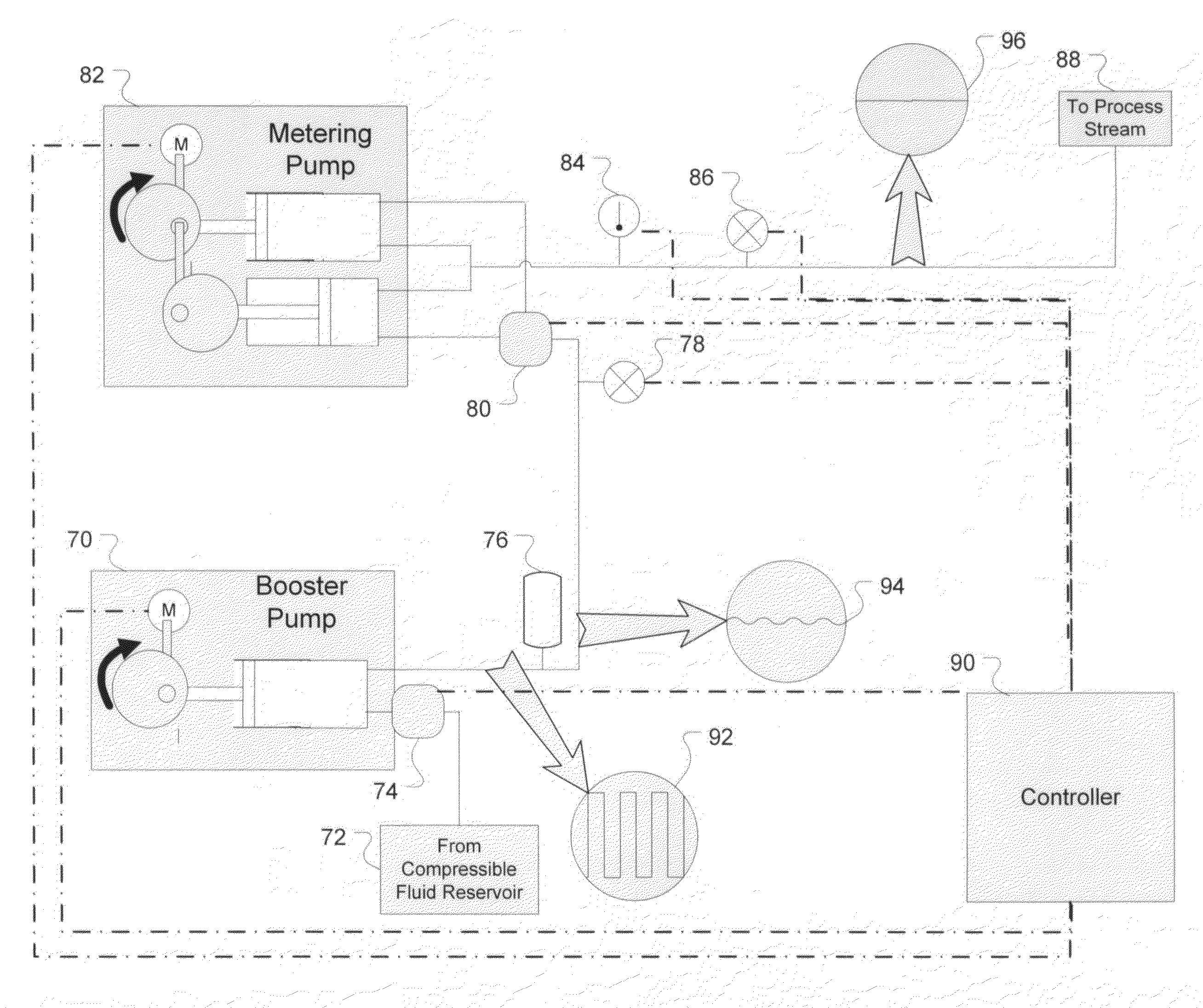
[0076]An alternative embodiment of the invention is displayed in FIG. 9. Booster pump 100 receives compressible fluid from reservoir 102. The fluid is chilled at prechiller 104 prior to entering the booster pump. On exit from the booster, the fluid passes optional pulse dampener 106 and the flow is then split between back pressure regulator (BPR) 108, which returns a portion of the flow to the low pressure side of the booster, and the flow path leading to metering pump 114. The later flow path also contains booster pressure sensor 110 and thermal conditioning device 112. The output flow stream of metering pump 114 leads to optional flow sensor 116, process pressure sensor 118 and finally to process stream 120. Controller 122 receives the signals of pressure sensors 110 and 118 and flow sensor 116. The controller also controls back pressure regulator 108 and prechiller 104. Optionally, the controller also controls the flow rate of booster pump 100 and / or metering pump 114.

[0077]In th...

second alternative embodiment

[0083]A second alternative embodiment of the invention illustrated in FIG. 10 demonstrates the extensibility the invention to a plurality of process streams. In this alternative embodiment, a single booster pump 124 supplies pressurized working fluid from compressible supply 152 to multiple metering pumps 126, 128, and 130 connected in series with the booster pump 124 and in parallel with each other. A pre-chiller installed between compressible fluid supply 152 and booster pump 124 to cool any incoming compressed gas to below its supply temperature and chill the booster pump head to prevent cavitation. Other flow devices including pulse dampener 132, booster pressure sensor 134 and thermal conditioning device 136 are positioned in the series line between the booster and all parallel metering pumps. Each metering pump supplies working fluid via a process pressure sensor 138, 140, or 142 respectively, to an individual process stream 144, 146, or 148 respectively. Not shown in FIG. 10 ...

third alternative embodiment

[0085]FIG. 11 displays a variation of the parallel processing stream concept from FIG. 10. In this case individual metering pumps 126-130 are replaced with a single drive, multi-output pump device 156. The implementation shown in FIG. 11 as metering pump 156 is a planetary gear pump mechanism which receives a single input and distributes flow evenly between multiple outputs. Alternatively, a pump that can also be considered is the radial piston pump comprised of multiple pairs of opposing pistons in a radial configuration. In this implementation opposing pistons are joined to the same process stream to deliver a pulseless output flow.

[0086]Addition of a single flow sensor 154 at the input to the metering pump 156 can indicate total flow that is then distributed evenly between the multiple processes. Pressure sensors 158-166 monitor pressure on each respective multiple outputs of metering pump 156 and provide pressure feedback to a controller of booster pump 124. Each multiple output...


PUM

PropertyMeasurementUnit
pressureaaaaaaaaaa
pressureaaaaaaaaaa
pressureaaaaaaaaaa

Abstract

An invention is claimed that enables the pumping of compressible fluids at high pressures when an accurate flow is desired. Two pressure sources, for example pumps plumbed in series, separate thermodynamic work, such as pressurization, at the first pressure source from a volumetric or matter metering function in the second pressure source. One example is a flowstream delivery for a chemical instrumentation system that is manufactured from relatively unsophisticated pumps yet delivers precise flows with low pulsation (<1 %) over pressures greater than 100 bar. An advantage of one embodiment allows the economical conversion of typical HPLC systems to state of-the-art supercritical fluid chromatography (SFC) systems with minimal modification to system components.

Description

STATEMENT OF PRIORITY[0001]This application claims the benefit of U.S. Provisional Application No. 61 / 075,251 filed 24 Jun., 2008.FIELD OF THE INVENTION[0002]The present invention relates to methods and systems for pumping compressible fluids. More specifically, it relates to pumping compressible fluids in high pressure applications.BACKGROUND[0003]Industrial pumping takes many forms, all with the general requirement of transporting fluids or slurries through a process stream. Pumps are selected based on the application requirements including head pressure, metering accuracy, temperature, particle tolerance, fluid viscosity, cost, safety, service rate and a variety of other parameters. Pumps can generally be classified in two categories. Positive displacement pumps isolate discrete volumes of the working fluid and force them to move in a controlled direction. Kinetic pumps operate by adding kinetic energy to the system which creates a local increase in fluid velocity. Kinetic energy...

Claims


Application Information

Patent Timeline
Patent Type & Authority Applications(United States)
IPC IPC(8): F04B25/00B23P17/00B23P11/00
CPCF04B11/0075F04B23/06G01N30/32Y10T29/49716G01N2030/326Y10T29/49826G01N30/34Y10T137/86139B01D15/40F04B49/00F04B13/00F04B23/04
Inventor BERGER, TERRY A.FOGELMAN, KIMBER D.WIKFORS, EDWIN E.STAATS, III, L. THOMSONCOLGATE, SAMUEL O.CASALE, MICHAEL A.
Owner AGILENT TECH INC
Why Eureka
Try Eureka