

Method producing common rail locally reinforced common rail
a technology of common rails and local reinforcements, applied in the direction of special fuel injection equipment, machines/engines, non-electric welding equipment, etc., can solve the problems of zone fatigue fracture, deformation and workability degradation, and fluid pressure fluctuation-induced fatigue fracture, etc., to achieve excellent fatigue strength
- Summary
- Abstract
- Description
- Claims
- Application Information
AI Technical Summary
Benefits of technology
Problems solved by technology
Method used
Image

Examples
example
[0093]In the following, an explanation is made with regard to the prototyping of a common rail for verifying the invention effects and to the results of internal pressure fatigue testing conducted.
[0094]Common rails like that illustrated in FIG. 17 were each fabricated as follows. First, a common rail body 51 measuring 230 mm in length, 40 mm in width and 30 mm in thickness and holders 52 measuring 25 mm in height, 24 mm in outside diameter and 4 mm in thickness were fabricated. Utilizing laboratory scale vacuum-melting or practical steel plate production equipment, a steel of a chemical composition falling in the range of one of the first to fourth aspects of the present invention was produced in an amount of 100 kg to 300 ton by vacuum melting or ordinary blast furnace—converter—secondary refinement—degassing / trace element addition—continuous casting—hot rolling. The steel was processed and shaped into the form shown in FIG. 17. Next, the rail body was formed with 1) a 10 mm-diame...
PUM
| Property | Measurement | Unit |
|---|---|---|
| pulse energy | aaaaa | aaaaa |
| thickness | aaaaa | aaaaa |
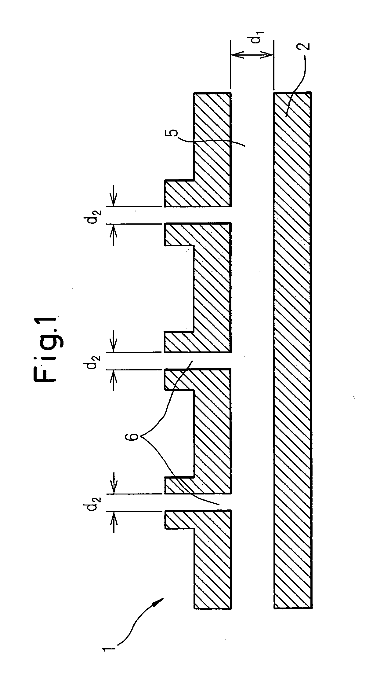
| diameter d2 | aaaaa | aaaaa |
Abstract
Description
Claims
Application Information