Electric motors

a technology of electric motors and motors, applied in the direction of electric energy management, electric devices, driver interactions, etc., can solve the problems of increased electromagnetic interference (emi) noise, reduced switching loss, and compounded problem of switching speed and emi noise, so as to protect the seal from excessive wear and tear

Active Publication Date: 2010-06-03
PROTEAN ELECTRIC LIMITED
View PDF27 Cites 41 Cited by
  • Summary
  • Abstract
  • Description
  • Claims
  • Application Information

AI Technical Summary

Benefits of technology

[0020]Control of the currents in the coils of the motor is enhanced because the current in each coil sub-set can be controlled independently of the current in another coil sub-set. Because all of the coils of each coil set are not connected in series, the coil or coils of each coil sub-set can have a larger number of turns. The increased number of turns in each coil increases the overall inductance of the motor. This means that lower currents can be used in the coils of each coil sub-set, which leads to fewer heat dissipation problems, and which allows smaller switching devices to be used. The use of smaller switching devices in turn allows for faster switching speeds and lower switching losses.
[0064]A further aspect of the invention is a motor comprising a cooling arrangement. The motor includes a plurality of coils arranged around a circumference and a cooling channel disposed immediately adjacent the plurality of coils through which a coolant fluid may circulate by being pumped or by convective flow. This aspect uses a multi faceted cooling plate, which encloses the windings on three sides and provides faces for the attachment of electronic power devices, a dump power device and a dump resistor. The stator assembly comprising the coils, teeth and back iron is assembled directly onto the cooling plate. The assembly is then potted onto the cooling plate using thermally conductive material, such as epoxy filled with aluminium oxide or aluminium nitride or carbon, for example. This potting process is important due to the mechanical integrity imparted to the whole assembly, all parts are as one and more able to withstand vibration and shock. The potting further improves the electrical strength of the insulation system in that it prevents any air pockets within the winding system. Because of the high switching speeds dv / dt is high and this induces electrical stress in the insulation medium of the windings. Air pockets would risk ionisation and lead to early failure of the insulation. In electronically controlled motors or generators this insulation breakdown brought on by the repeated electrical stress induced through the switching events is a major reliability issue, the potting reduces this risk by a very large degree. Potting is best done under vacuum, but low viscosity potting material can be used in atmospheric pressure. The potting is of importance in improving the thermal conductivity between the heat generating windings and laminations of the back iron and the heat sink cooling plate with it's cooling fluid inside. The potting is further of great benefit in that it allows the winding system to be fully immersed in water with no risk of electrical failure. This is important due to the need to make the electrical system immune to condensation or other water ingress.

Problems solved by technology

Typical power electronic switches including the Metal Oxide Silicon Field Effect Transistor (MOSFET) and the Insulated Gate Bipolar Transistor (IGBT) exhibit two principal losses: switching losses and conduction losses.
While switching losses decrease with switching speed, a faster switching speed also leads to increased electromagnetic interference (EMI) noise.
This problematic trade off between switching speed and EMI noise is compounded at higher power ratings (e.g. for a larger motor), since larger switches are required.
This inductance impacts the switching speed of the power device and the switching speed of a power device is typically therefore limited by its physical size.
Accordingly, for high power ratings larger switches must be used, but larger switches involve slower switching speeds and therefore larger switching losses.
Moreover, the cost of a power device increases roughly with the square of the size of the device.
Conduction losses also increase with increased power.
This imposes serious thermal management problems for the motor since, for example, a doubling of the power leads to a four fold increase in thermal losses.
Extracting this heat without elevating the temperature of the device above its safe operating level becomes the limiting factor in what power the device can handle.
Indeed, today larger power devices having intrinsic current handling capabilities of, for example, 500 A are restricted to 200 A due to thermal constraints.
For higher power motors, these two factors inhibit the effectiveness of PWM as a control system because the current in the motor coils rises more rapidly (due to the low inductance of the motor due to the fewer number of turns in the coils) but the PWM control is more coarse (due to the slow switching speed achievable using high power switching devices).
However, the chokes are typically as large or larger than the motor itself and as they carry the full current they dissipate a large additional heat loss as well as being a substantial extra volume, weight and cost.
Other problems with known motors relate to their manufacture.
Winding the coils of the motor, as well as terminating the connections between each coil sub-set interspersed around the motor periphery is a labour intensive task.
The thick wire (e.g. copper wire) typically used in motor windings is difficult to manipulate and in many motor designs, access to the innards of the motor for installing the coils and their interconnections is limited.
Known coil mounting systems are also bulky and have limited heat dispersing capabilities.
A vehicle relying on wheel traction to provide a resultant locomotive force suffers from the phenomenon of wheel skid.
If this force is exceeded, then a wheel slip or skid will occur.
These traction control systems require expensive mechanical parts and do not always provide the best performance.
For example, ABS brakes tend to shudder violently as they are operated on a crude on / off basis.

Method used


Image

  • Electric motors
  • Electric motors
  • Electric motors

Examples


Embodiment Construction

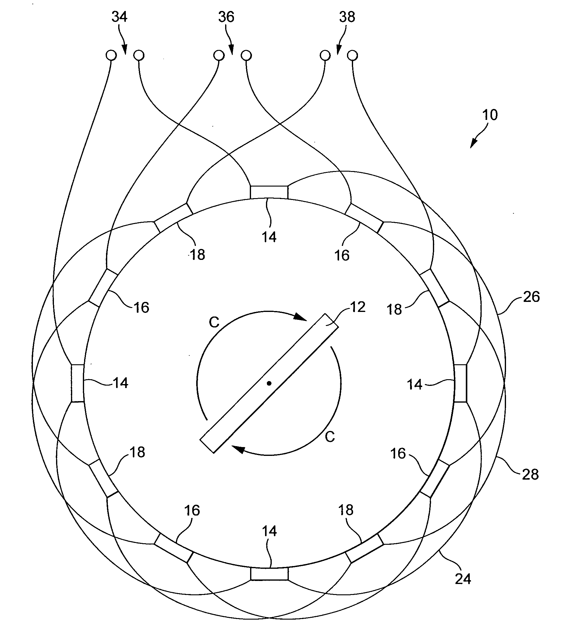
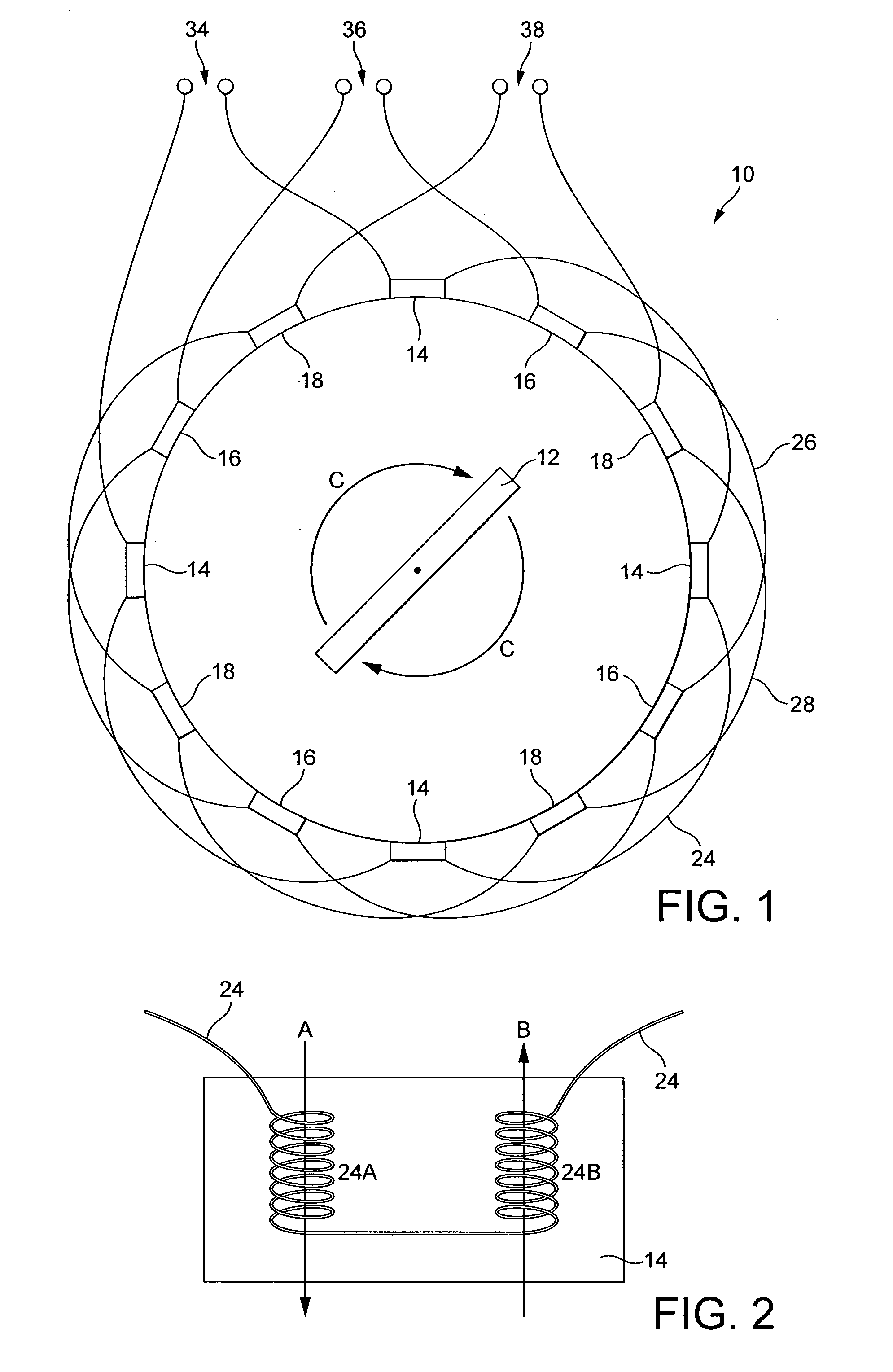
[0091]The embodiment of the invention described is an electric motor for use in a wheel of a vehicle. The motor is of the type having a set of coils being part of the stator for attachment to a vehicle, radially surrounded by a rotor carrying a set of magnets for attachment to a wheel. For the avoidance of doubt, the various aspects of the invention are equally applicable to an electric generator having the same arrangement. In addition, some of the aspects of the invention are applicable to an arrangement having the rotor centrally mounted within radially surrounding coils.

Physical Arrangement

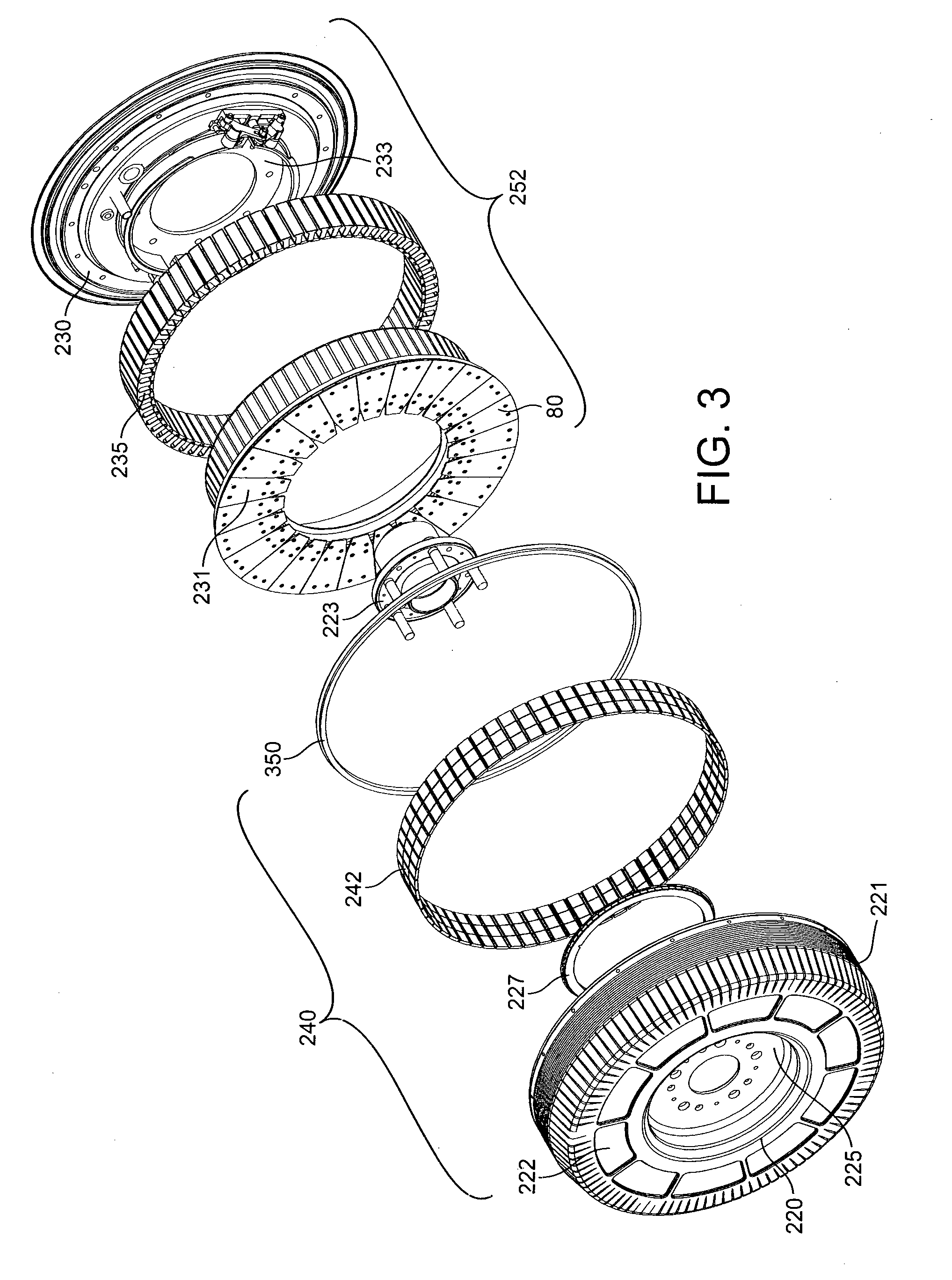
[0092]The physical arrangement of the embodying assembly is best understood with respect to FIGS. 3 and 4. The assembly can be described as a motor with built in electronics and bearing, or could also be described as a hub motor or hub drive as it is built to accommodate a separate wheel.

[0093]Referring first to FIG. 3, the assembly comprises a stator 252 comprising a rear portion 230 forming ...


PUM

PropertyMeasurementUnit
intrinsic current handling capabilitiesaaaaaaaaaa
voltageaaaaaaaaaa
voltageaaaaaaaaaa

Abstract

An electric motor includes one or more separate coil sets arranged to produce a magnetic field of the motor. The electric motor also includes a plurality of control devices coupled to respective sub-sets of coils for current control. A similar arrangement is proposed for a generator. A coil mounting system for an electric motor or generator includes one or more coil teeth for windably receiving a coil for the motor and a back portion for attachably receiving a plurality of the coil teeth. A traction control system and method for a vehicle having a plurality of wheels independently powered by a respective motor. A suspension control system and method for a vehicle having a plurality of wheels, each wheel being mounted on a suspension arm of the vehicle and being independently powered by a respective motor.

Description

FIELD OF THE INVENTION[0001]The invention relates to electric motors or generators and to a traction control system.BACKGROUND OF THE INVENTION[0002]Known electric motor systems typically include a motor and a control unit for controlling power to the motor. Known types of electric motor include the induction motor, brushless permanent magnet motor, switched reluctance motor and synchronous slip ring machine. Three phase electric motors are the most common kind of electric motor available.[0003]FIG. 1 shows a schematic representation of a typical three phase motor. In this example, the motor includes three coil sets. Each coil set produces a magnetic field associated with one of the three phases of the motor. In a more general example, N coil sets can be used to produce an N-phase electric motor. Each coil set can include one or more sub-sets of coils which are positioned around a periphery of the motor. In the present example, each coil set includes four such sub-sets—the coil sub-...

Claims


Application Information

Patent Timeline
Patent Type & Authority Applications(United States)
IPC IPC(8): B60B39/00H02K1/08H02K3/28H02K15/02B60K1/00
CPCB60G2204/30Y02T10/7275B60K7/0007B60L7/006B60L7/16B60L7/22B60L2220/18B60L2220/44H02K5/20H02K7/14H02P3/18Y02T10/641Y02T10/7258B60L3/0038B60L3/0046B60L3/0069B60L3/04B60L7/12B60L11/1805B60L15/2009B60L2240/423B60L2250/26B60L2260/28H02K7/006Y02T10/7005Y02T10/70Y02T10/648B60L2200/26Y10T29/49462Y10T29/49009B60G2300/50Y02T10/72B60L3/102B60L2240/465H02K7/106H02K11/0094B60L50/52B60L58/12Y02T10/64H02K9/227H02K5/203H02K1/148H02P6/08H02K11/33H02K1/20H02K3/28B60L15/20B60L15/2036B60L15/32H02K11/30B60L7/18H02K1/2786H02K1/28H02K5/10
Inventor BOUGHTWOOD, MARTIN
Owner PROTEAN ELECTRIC LIMITED
Why Eureka
Try Eureka