

Exhaust gas processing system and method for rotary hearth type reducing furnace
a processing system and rotary hearth technology, applied in the field of exhaust gas processing system and method for rotary hearth type reducing furnace, can solve the problems of limiting the conventional reducing iron manufacturing process, affecting the efficiency of heat exchangers, and blocking the flow channel of exhaust gas, so as to achieve the effect of recovering the sensible heat of exhaust gas
- Summary
- Abstract
- Description
- Claims
- Application Information
AI Technical Summary
Benefits of technology
Problems solved by technology
Method used
Image

Examples
example 1
(Confirmation of the Effects of the Basic Configuration of the Invention)
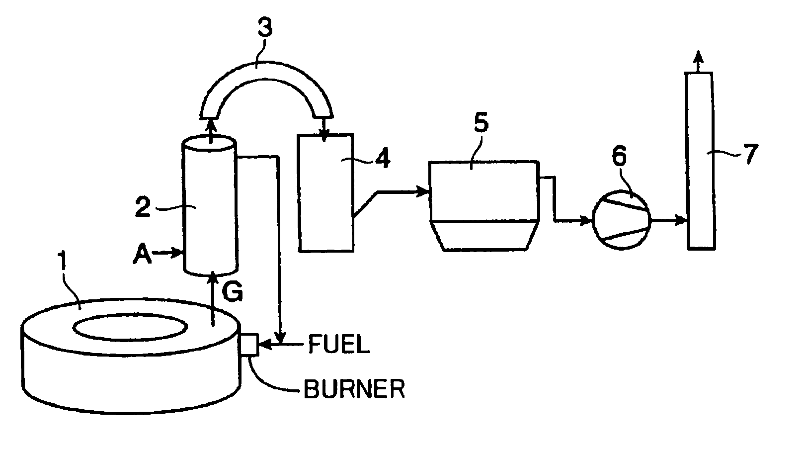
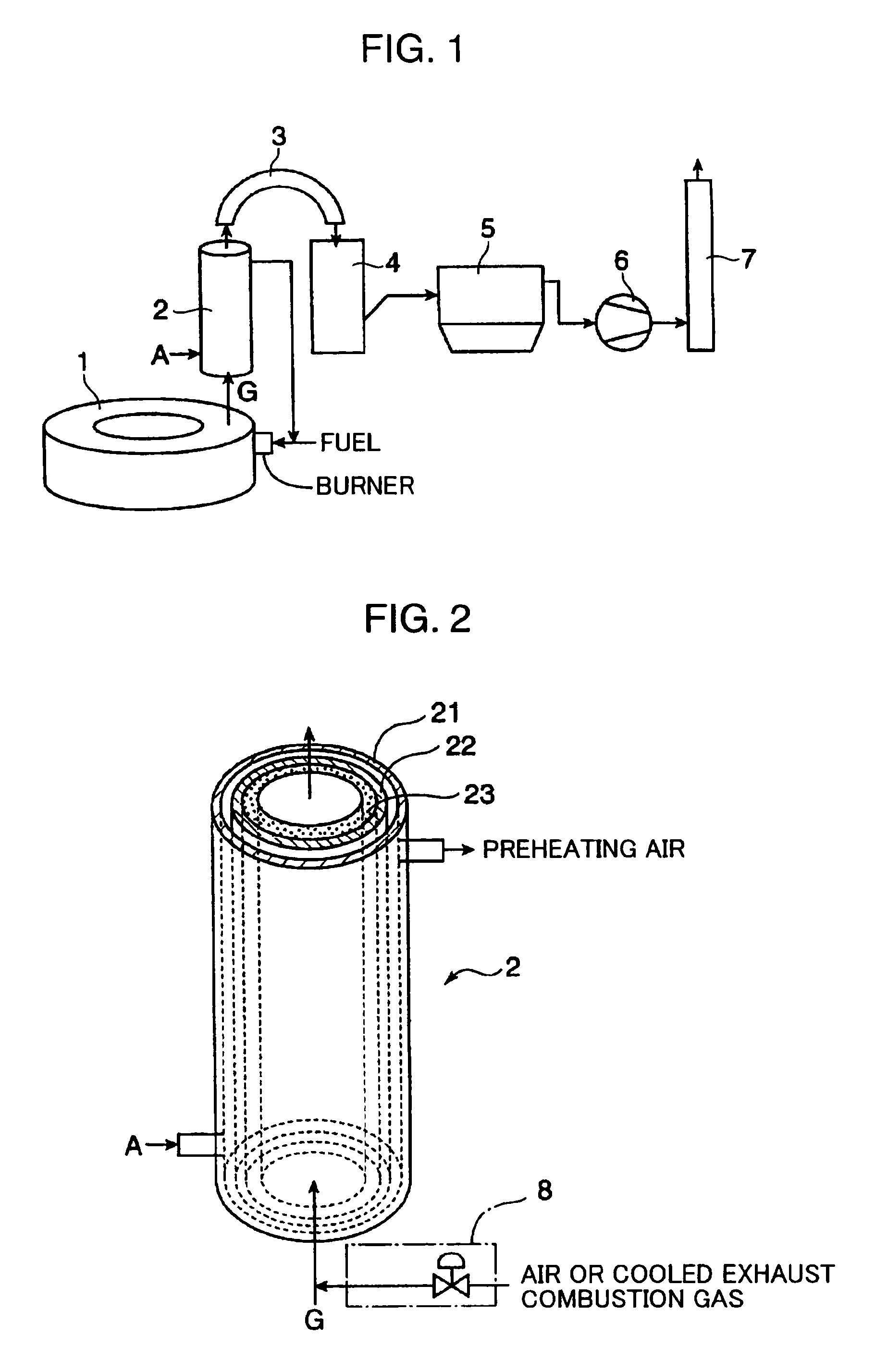
[0063]In order to confirm the effects of the invention, experiments using the exhaust gas processing system shown in FIG. 1 were conducted. In Example 1 was used, as the radiant heat exchanger 2 , a exchanger including an inner cylinder 22 formed of a steel plate made of stainless steel with an inner diameter of 1.55 m, a length of 8.2 m, and a heat transfer area of 40 m2 and a refractory 23 formed of a silicon carbide refractory (the SiC content is 60% by mass and the rest are chiefly Al2O3 and SiO2) with the thickness of 50 mm and laid to the inner cylinder 22 by casting so as to cover the inner surface thereof. As the exhaust gas cooling tower 4 is used one in which spraying water and introduction of air at normal temperature into the exhaust gas is performed.
[0064]An exhaust gas at about 1,450° C. was exhausted from the rotary hearth furnace 1 at a flow rate of about 11,600 Nm3 / h, and air at normal temperat...
example 2
(Confirmation of Influence of SiC Content in Silicon Carbide Refractory)
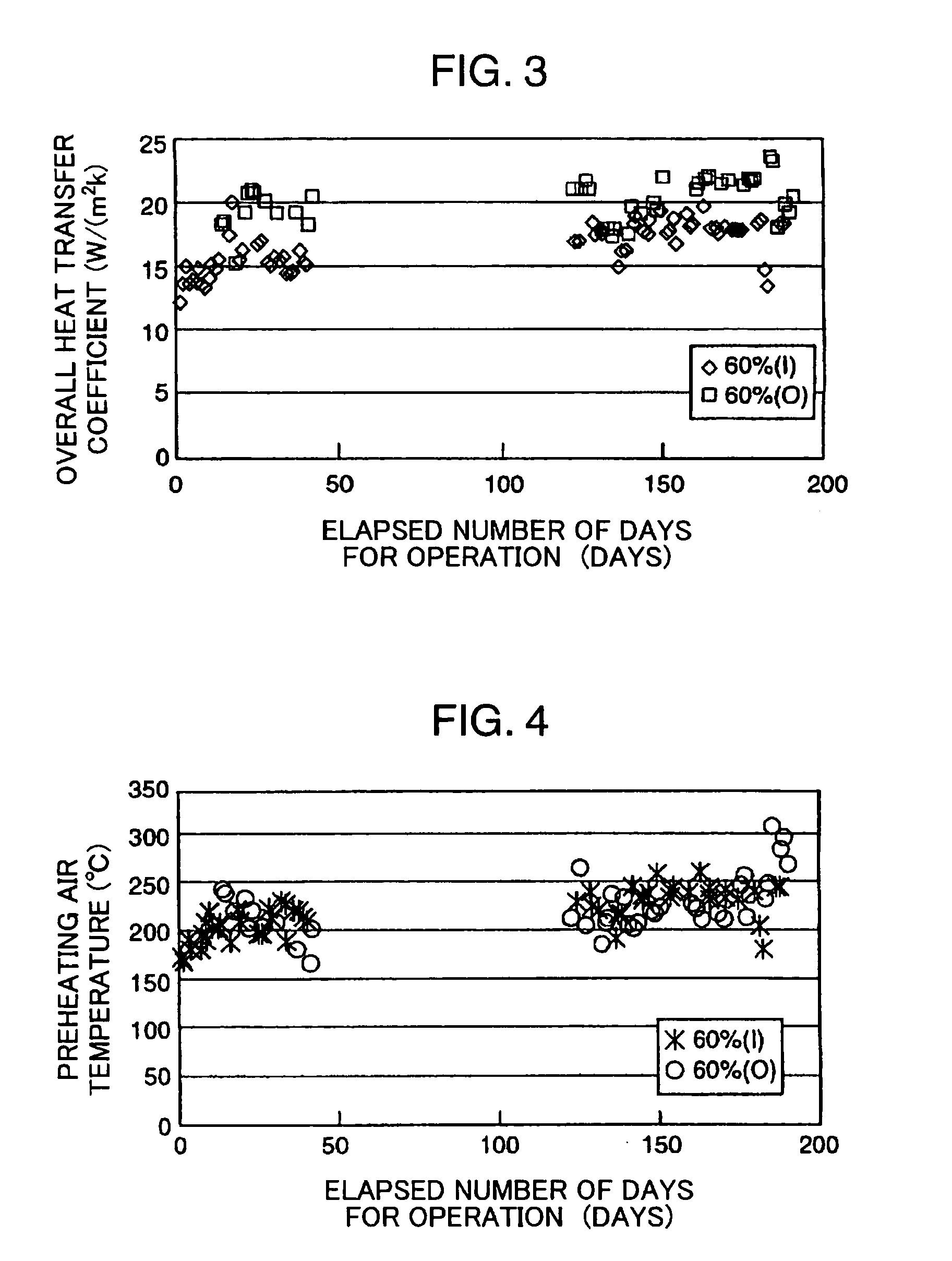
[0069]In Example 2, in the exhaust gas processing system according to Example 1 above, a refractory having a SiC content of 80% by mass was used as the silicon carbide refractory applied on the inner side of the inner cylinder 22 of the heat exchanger 2 instead of the silicon carbide refractory having a SiC content of 60% by mass. The operation was continued for about 190 days under the operation conditions same as those in Example 1.
[0070]FIG. 5 and FIG. 6 show changes of the overall heat transfer coefficient and the preheating air temperature of the heat exchanger 2 during the operation period. In FIG. 5, data during the reduction operation on and after about 150 days contain a rather low overall heat transfer coefficient, which does not represent deterioration of the heat transfer performance but is attributed to a reduction in amount of heat exchange because of the heat exchange performed under conditions wh...
example 3
(Influence of Thickness of Silicon Carbide Refractory)
[0076]The thickness of the silicon carbide refractory was 50 mm in each of Examples 1 and 2 above. Refractory thickness of 100 mm reduces an amount of heat exchange by about 15% compared with the thickness of 50 mm, and thickness of 200 mm reduces an amount of heat exchange drops by about 27% compared with the thickness of 50 mm. It is therefore preferable that the highly thermal conductive refractory is made as thin as in its application.
PUM
| Property | Measurement | Unit |
|---|---|---|
| temperature | aaaaa | aaaaa |
| temperature | aaaaa | aaaaa |
| exhaust gas temperature | aaaaa | aaaaa |
Abstract
Description
Claims
Application Information