This specialized circuitry, in conjunction with the 10 to 25 CCFLs, is not as energy efficient as providing the same amount of lumens with a plurality of white or ultra
bright Light Emitting Diodes (LEDs).
Another drawback of CCFL backlighting is that CCFLs contain mercury.
Mercury is well known toxic
metal that if not disposed of properly has an
adverse effect on the environment.
CCFLs have a limited average expected
operating life of between 10 to 20 thousand hours.
Thus, if a monitor using CCFL backlighting is left on for about 2⅓ years (approximately 20 thousand hours of
continuous use) one or more of the CCFL tubes within the monitor will most likely fail.
Another CCFL aging problem is that dim spots may appear in portions of the CCFL tubes.
Another drawback of using CCFLs is that CCFLs must be placed a distance from the back of the LCD screen so that the light emitted from a plurality of spaced CCFL tubes can diffuse in order to provide a substantially uniform brightness across the entirety of the LCD screen.
This issue becomes important in television display and monitor applications where many LEDs must be connected in series.
Furthermore, such hard switched topologies are not suitable for operation at frequencies above about 100 kHz.
These large
capacitor values must also be rated for an
operating voltage of 350 volts or more, thereby making them relatively expensive components.
In addition, when such high valued capacitors (greater than 10 μF) are used there is the potential for the creation of acoustic
noise at the
pulse width modulated (PWM) dimming frequencies used on the LEDs.
The
dielectric materials, because of their size, are prone to a piezoelectric
acoustic effect, which generates audible sound or sounds emanating from the capacitors.
The prior hard switched boost topologies that provide an output voltage in the range of about 300 to 350 volts (or even higher) have
power loss inefficiencies resulting from the continuous charging and discharging of parasitic capacitances associated with the
solid state components of the driver circuitry.
The above calculation clearly shows that one drawback of hard switched boost topologies operating at switching frequencies above 100 kHz, for example 500 kHz, can result in at least 2.25 watts of power being lost on a continuous operational basis.
Another drawback of hard switched
driver circuit topologies is that although it is advantageous to operate such boost regulator circuitry in what is called a Discontinuous
Current Mode (DCM), which helps to reduce the output diodes
reverse recovery losses, such DCM operation produces severe
high frequency spikes and undesirable switching node
ringing.
Such severe
high frequency spikes produce EMI and other electrical
noise that is difficult to mitigate and that may have a negative affect on other nearby circuitry.
But, due to power loss and
circuit design limitations, the
switching frequency of such prior boost regulator circuits has been limited to a frequency of about 100 kHz to perhaps 250 kHz.
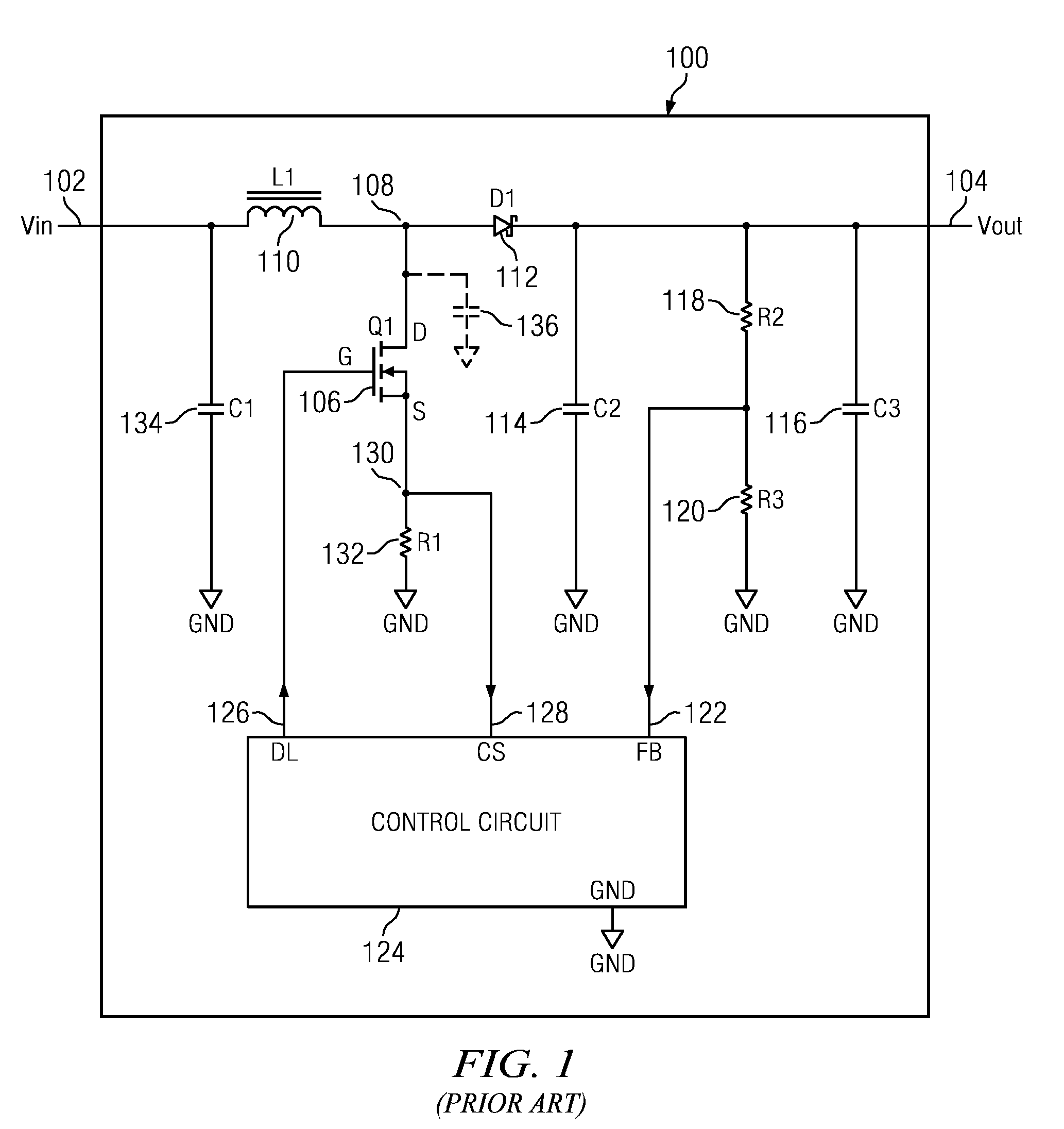
All actual circuit elements such as inductors, diodes, and transistors have internal
capacitance, which can cause their behavior to depart from that of “ideal” circuit elements.
When the voltage does not change very quickly, as in
low frequency circuits, the extra current required is usually negligible, but when the voltage is changing at higher and higher frequencies, the extra current becomes a large quantity and can dominate the operation of the circuit.
This power loss is discharged in the form of heat dissipation.
Furthermore, in addition to the power loss and heat dissipation, the switching transistor 106 is encountering and being driven from a very
high voltage to a very
low voltage and vice versa at the
switching frequency.
If this
high voltage and
high current found across and through the switching transistor is integrated over time, one finds that it is the source of an additional power loss called the “switching loss” of the transistor.
This power loss occurs during the
switching time as the transistor switches on and off.
Thus it is easy to see as switching frequency increases the amount of power loss also increases.
There is a balance that must be made between increasing the switching frequency of a hard switched boost regulator, which allows the
reactive components of the boost regulator to be smaller and smaller, but which increases the power loss or inefficiency of the same circuit.
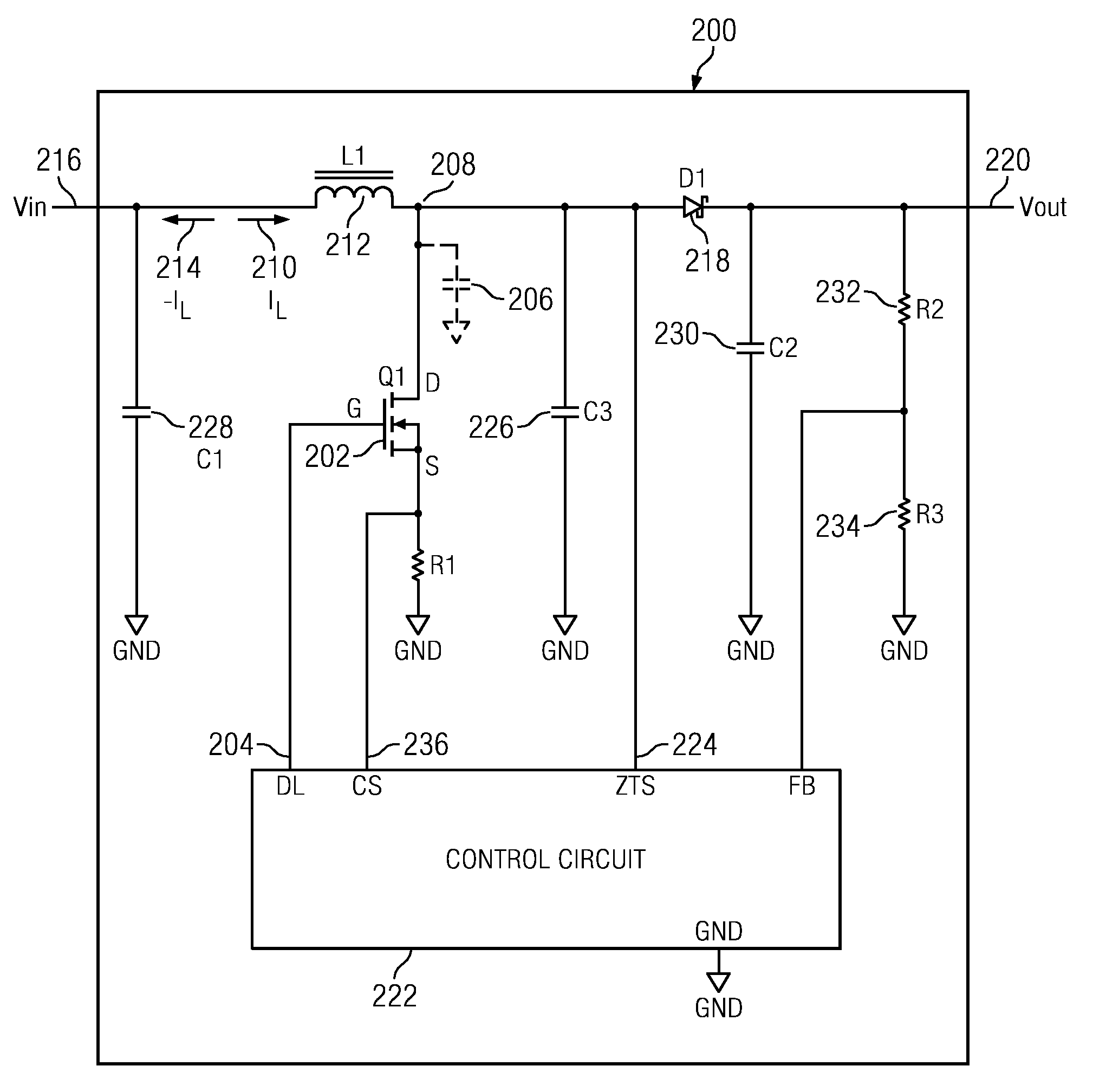
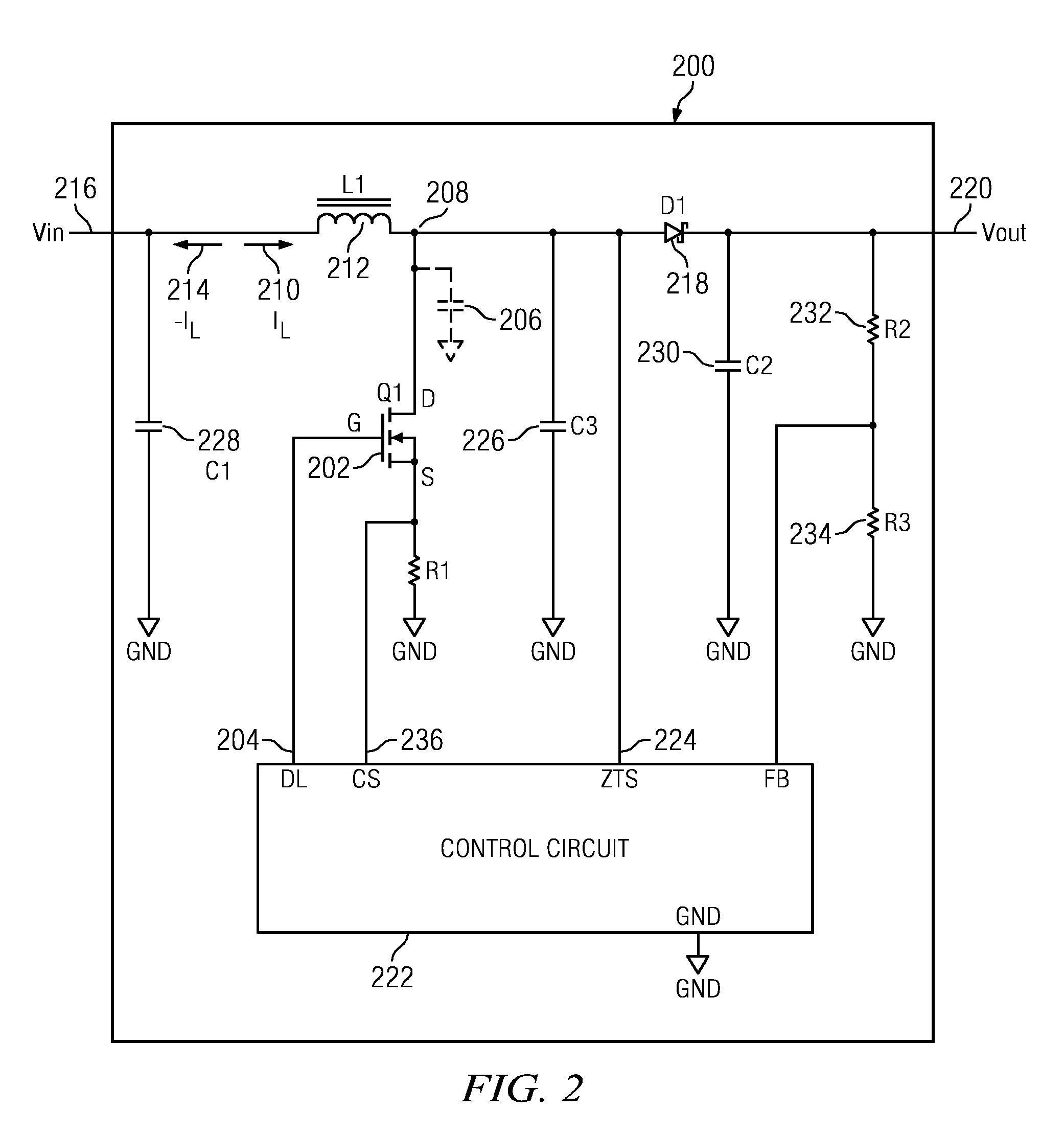
Yet another drawback of the prior boost regulator circuitry is due to the
diode recovery losses in the D1
diode 112.
Reverse biasing a
diode that has a very large voltage potential in a very short period of time causes the diode's
parasitic capacitance charges to have to dissipate extremely quickly.
During the instant that the virtual short exists across the diode, a very high voltage and a very
high current exist therein, which not only must be dissipated as power loss heat, but also creates severe
high frequency spikes of current.
These high frequency current spikes also result in emitting switching noise in the form of
electromagnetic interference (EMI), which is transmitted by the circuit and could be coupled or picked up by other nearby unrelated circuitry.
Such EMI
coupling could potentially cause circuit malfunctions or dropped data in other circuits.
These
high voltage capacitors are not only expensive, but because of their high values and
large size, which is required for operating at 100 to 200 kHz frequencies, the
dielectric plates within the high voltage
ceramic capacitors produce a piezoelectric acoustic noise generated due to a
Pulse Width Modulated (PWM) DIM frequency used in many LED applications for brightening and dimming the lumen output of the LEDs (not specifically shown).
Of course, such noise is undesirable if emitted from a television, monitor or other LCD
display device.
It should be noted that electrolytic capacitors are generally not desirable and whenever possible avoided in such prior circuits because their
life span is much shorter than the high voltage
ceramic capacitors.
Furthermore, electrolytic capacitors are much larger and bulkier than ceramic capacitors.

