Heat resisting ultrafine fibrous separator and secondary battery using the same

a technology of ultrafine fibrous separator and secondary battery, which is applied in the manufacture of final products, record information storage, synthetic resin layered products, etc., can solve the problems of short circuit, insufficient to be used for batteries having a high energy density and a high capacity in an aspect of thermal endurance, and achieve excellent ionic conductivity, low thermal contraction, and high thermal endurance

Active Publication Date: 2010-09-16
KOREA INST OF SCI & TECH
View PDF3 Cites 69 Cited by
  • Summary
  • Abstract
  • Description
  • Claims
  • Application Information

AI Technical Summary

Benefits of technology

[0021]A heat-resisting ultrafine fibrous separator in accordance with the present invention has a shutdown function, low thermal contraction, thermal endurance, excellent ionic conductivity and excellent adhesive property with an electrode, so a battery having excellent cycling characteristics and having a high-energy density and a high capacity can be prepared. Since forming an ultrafine fibrous layer as well as removing solvent and forming pores are performed at the same time through an electrospinning process, so it can be prepared in a very simple and easy process compared to the process in the conventional art.
[0022]Therefore, the heat-resisting ultrafine fibrous separator is particularly useful to electrochemical devices (a secondary battery including a lithium ion secondary battery, a lithium ion polymer battery and a super capacitor) requiring high thermal endurance and thermal stability, such as a hybrid electric automobile, an electric automobile and a fuel cell automobile.

Problems solved by technology

When the separator is melt as the temperature goes higher, then a big hole is made, causing a short circuit between the anode and the cathode.
When a battery abnormally generates heat, a polyethylene separator is contracted at a temperature more than 150° C. and exposes the electrode portion thereof, indicating the possibility to cause the short circuit.
A lithium ion battery using a polyolefine separator and a liquid electrolyte, or a lithium ion polymer battery using a gel-coated polyolefine separator or using a gel polymer electrolyte film, in a conventional art, is very insufficient to be used for a battery having a high-energy density and a high capacity in an aspect of thermal endurance.
Therefore, the thermal endurance required from batteries having a high capacity and a large size for automobiles is not satisfying a requirement for safety.
The heat-resisting thin layer provides porosity through the solvent extraction, and the polyolefine separator is limited to use, of which air permeability is less than 200 sec / min.
However, immersion in the heat-resisting resin causes pores of the polyolefine separator to be blocked and the movement of the lithium ion to be restricted, resulting in deterioration of charging / discharging characteristics.
Thereby, even though thermal endurance is secured, the need for a large-capacity battery for automobiles is not satisfied.
Further, even though the porous structure of the polyolefine porous film is not blocked by the immersion of the heat-resisting resin, the porosity of the polyolefine separator which is conventionally used is about 40% and the size of the pore is several tens nm, so there is limited on ion conductivity for large capacity batteries.
But, the preparation process for the heat-resisting polymer layer, in which the heat-resisting polymer layer is deposited and then is immersed-washed-dried in the coagulation solution, is very complicated and requires high preparing cost.
However, even though thermal endurance is secured as required, in the aspect of ionic conductivity, the movement of the ion in the support or the heat-resisting aromatic polymer layer is still limited, similar to that of the separator or the gel electrolyte in the conventional lithium ion battery.
Therefore, the thermal endurance and the ionic conductivity still can not be satisfactory at the same time, there is nothing mentioned about the shutdown function of the separator and it is not still satisfactory for a battery having a high-energy density and a large capacity, such as for automobiles requiring excellent functions in severe conditions such as thermal endurance and rapid charging / discharging.

Method used


Image

  • Heat resisting ultrafine fibrous separator and secondary battery using the same
  • Heat resisting ultrafine fibrous separator and secondary battery using the same
  • Heat resisting ultrafine fibrous separator and secondary battery using the same

Examples


example 1-1

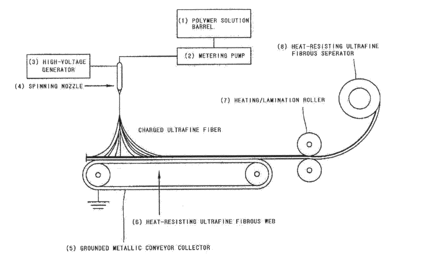
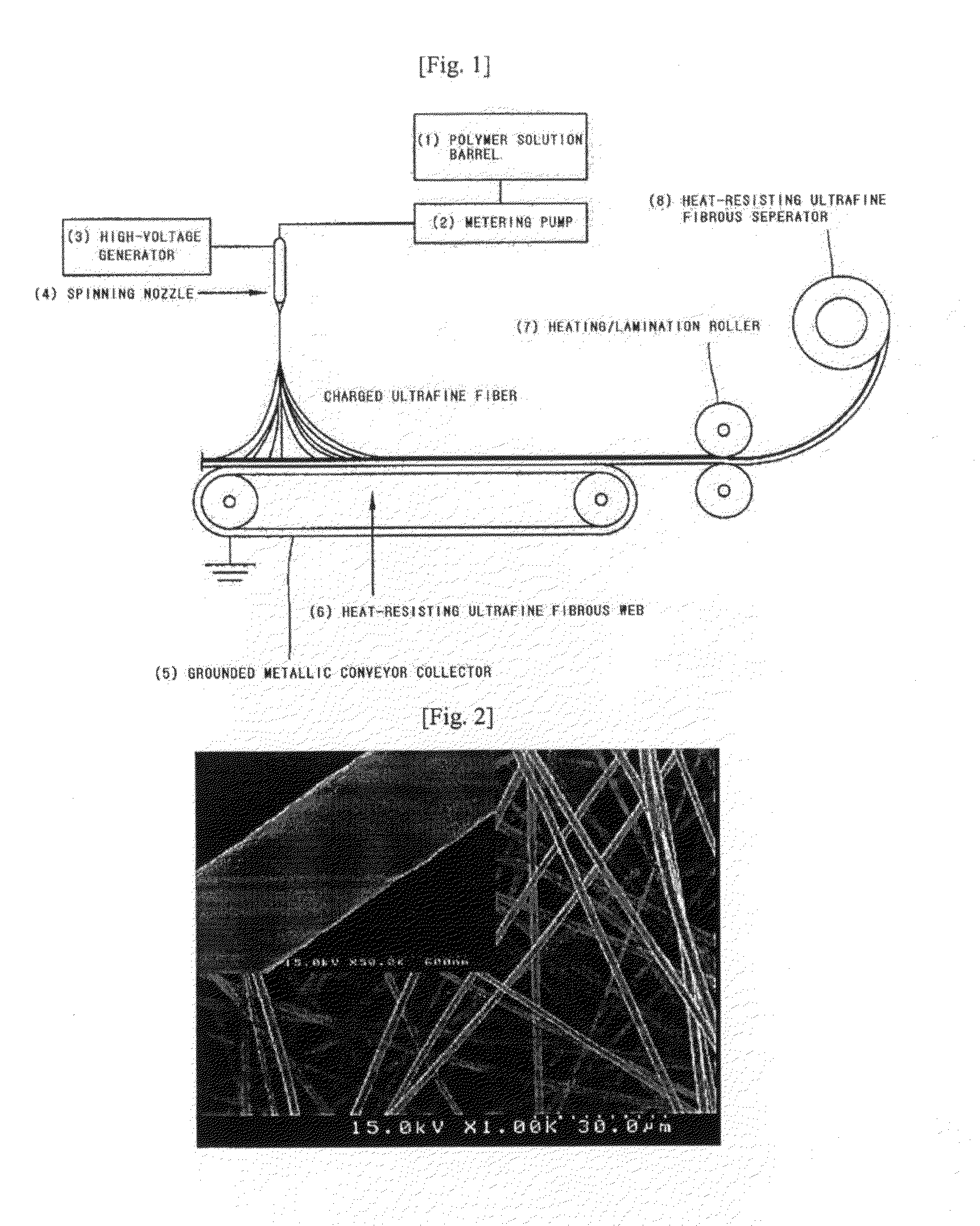
[0054]In order to prepare a heat-resisting polymer ultrafine fiber by an electrospinning, 10 g of poly(meta-phenylene isophthal amide) and 5 g of poly (vinylidene fluoride-co-hexafluoropropylene) copolymer (Kynar 2801) are added into 85 g of dimethylacetamide (DMAc), and then stirred at a room temperature, thereby a heat-resistant polymer resin solution is obtained. Also, the heat-resisting polymer resin solution is inputted to a barrel of an electrospinning apparatus as shown in FIG. 1, and then discharged using a metering pump at a speed of 150 μl / min. Herein, electric charge of 17 kV is applied to a spinning nozzle (4) using a high-voltage generator, so that ultrafine fiber web with the thickness of 40 μm is prepared from a mixture of the poly(meta-phenylene isophthal amide) and the poly(vinylidene fluoride-co-hexafluoropropylene). That is, the fiber forming the separator includes a phase of a heat-resisting polymeric material and a phase of a swelling polymeric material.

[0055]An...

example 1-2

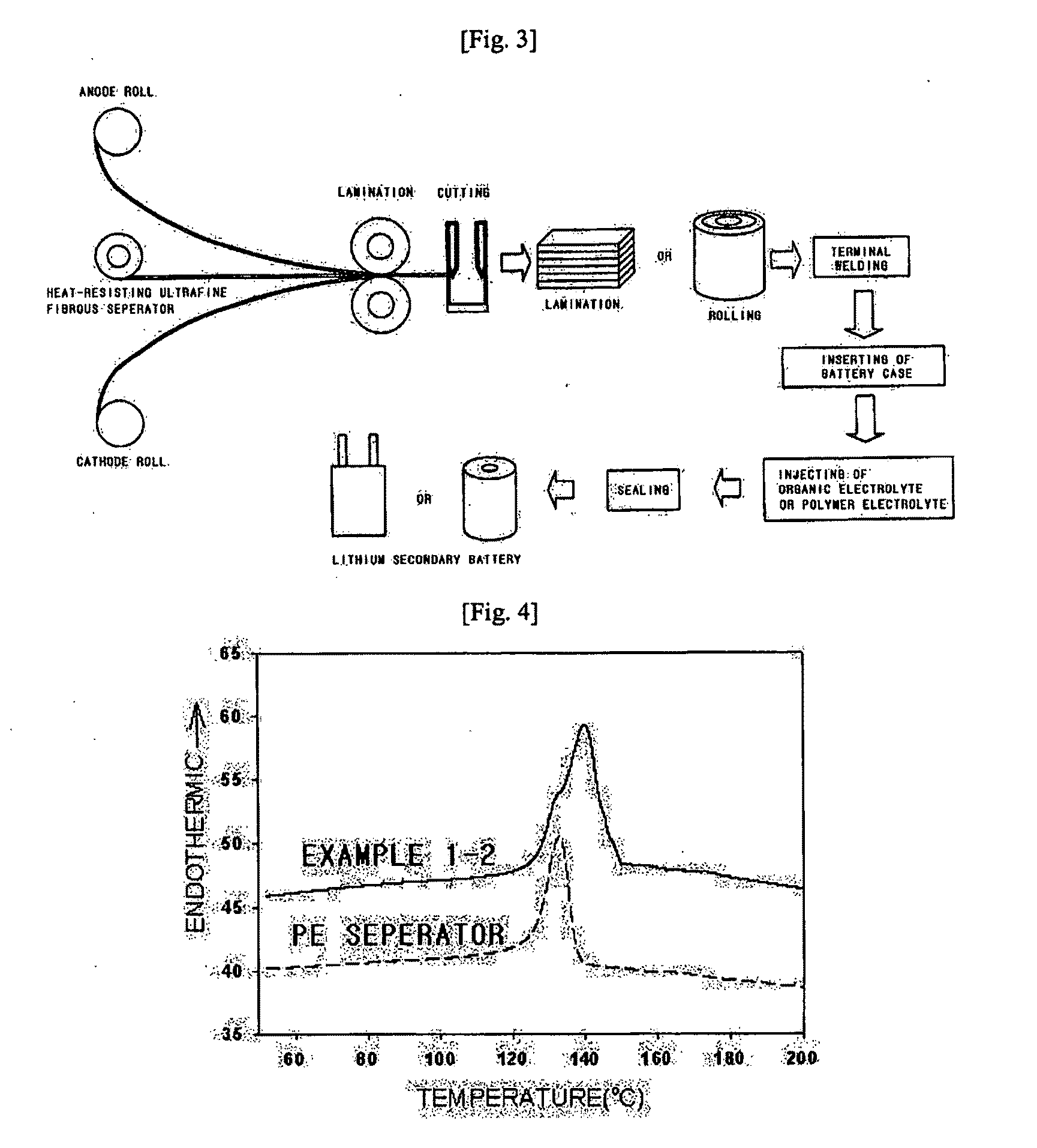
[0056]In order to prepare a heat-resisting polymer ultrafine fiber by an electrospinning, 15 g of poly(meta-phenylene isophthal amide) is added into 85 g of dimethylacetamide (DMAc), and then stirred at a room temperature, thereby a heat-resistant polymer resin solution is obtained. Also, 5 g of poly (vinylidene fluoride) [Kynar 761] is dissolved in 95 g of dimethylacetamide (DMAc), into which 10 g of polyethylene fine powders (0.1 μm) having 132° C. of softening point are dispersed to prepare a dispersed solution. Two polymer solutions are electrospun through separated spinning nozzles, respectively, in a same discharging speed, accordingly, a web which is a mixture of poly(meta-phenylene isophthal amide) ultrafine fibrous phase and poly(vinylidene fluoride) / polyethylene ultrafine fibrous phase and has the thickness of 40 μm is prepared. That is, the separator includes two kinds of fibers, one is a fiber including the fibrous phase of heat-resisting polymer material, the other is t...

example 1-3

[0058]A web which is a mixture of poly(meta-phenylene isophthal amide) ultrafine fibrous phase and poly(vinylidene fluoride) / polyethylene ultrafine fibrous phase and has the thickness of 60 μm an is prepared in the same method with the example 1-2, and then is laminated by compression at a temperature of 125° C., so that a heat-resisting ultrafine fibrous separator having the thickness of 20 μm is prepared. An apparent porosity, the electrolyte uptake (%), Shrinkage rates at the temperature of 120° C. and 150° C. of this separator are shown in Table 1.


PUM

PropertyMeasurementUnit
melting pointaaaaaaaaaa
sizeaaaaaaaaaa

Abstract

A heat-resisting ultrafine fibrous separator of the present invention is prepared by an electrospinning process, formed of ultrafine fibers of heat-resisting polymer resin having a melting point more than 1800 C or not having the melting point, or ultrafine fibers of polymer resin capable of swelling in an electrolyte, together with the ultrafine fibers of heat-resisting polymer resin. Also, polyolefine fine particles providing a shutdown function are dispersed in the heat-resisting resin or the polymer resin capable of swelling in the electrolyte. The heat-resisting ultrafine fibrous separator of the present invention has the shutdown function, low thermal contraction, thermal endurance, excellent ionic conductivity and excellent adhesive property with an electrode, so a battery having excellent cycling characteristics, and having high-energy density and high capacity can be prepared.

Description

TECHNICAL FIELD[0001]The present invention relates to a heat resisting ultrafine fibrous separator, and more particularly, to heat resisting ultrafine fibrous separator having a shut-down function, excellent thermal endurance and excellent ionic permeability, accordingly having excellent charging / discharging characteristics, and an electrochemical device using the same.BACKGROUND ART[0002]As the needs of the consumers have been changed due to digitization and high-efficiency of electronics products, a new trend is driven to develop thin and light batteries with high capacity by high-energy density. And, in order to deal with problems in the future energy and environment, the developments for hybrid electric vehicles or electric vehicles, and fuel cell vehicles have actively been progressed. Accordingly, large-sized batteries for an automobile electric power source are required.[0003]A secondary battery including a lithium ion secondary battery, a lithium ion polymer battery and a su...

Claims


Application Information

Patent Timeline
Patent Type & Authority Applications(United States)
IPC IPC(8): H01M2/16B32B5/02D04H3/14D04H1/56B32B5/16B32B5/00B32B3/26H01M50/414H01M50/417H01M50/489H01M50/491
CPCB32B5/26Y10T428/268B32B27/08B32B27/12B32B27/30B32B27/32B32B27/34D01D5/0015D01F6/12D01F6/605H01M2/162H01M10/0525Y02E60/122Y10T428/27Y10T428/254B32B27/02Y10T428/249921Y10T428/249953Y10T442/68Y10T442/60Y02E60/10H01M50/44Y02P70/50H01M50/417H01M50/491H01M50/414H01M50/489H01M50/411H01M50/463H01M50/403
Inventor JO, SEONG-MUKIM, DONG-YOUNGCHIN, BYUNG-DOO
Owner KOREA INST OF SCI & TECH
Why Eureka
Try Eureka