[0043]The apparatus of the present invention decreases the thermal cycling time needed for
DNA amplification over other Peltier-based systems. In embodiments of the present invention, 30 standard cycles of PCR can be completed in approximately 5 minutes, whereas known, conventional Peltier-based thermocyclers require about 10 minutes minimum. Another
advantage of the present invention is that larger reaction volumes of about 50 μL to about 250 μL can also be processed under rapid thermal cycling conditions, whereas other Peltier-based and pressurized gas instruments are limited to about 3-25 μL as in the systems of U.S. Pat. No. 6,556,940 to Tretiakov et al, and U.S. Pat. No. 6,472,186 to Quintanar et al. The ability to process larger reaction volumes is highly attractive for many applications as a means to increase PCR sensitivity or
dilution of inhibitors. In addition, the vessels provided in the present invention are ideally suited for rapid PCR because of the limited dimension critical for heat transfer when the vessels are placed within the thermocycler, yet the vessels are comparable in ease of loading / unloading and cost to standard PCR tubes. Fourth, the present invention is compatible with optical detection so that rapid amplification and detection may be carried out.
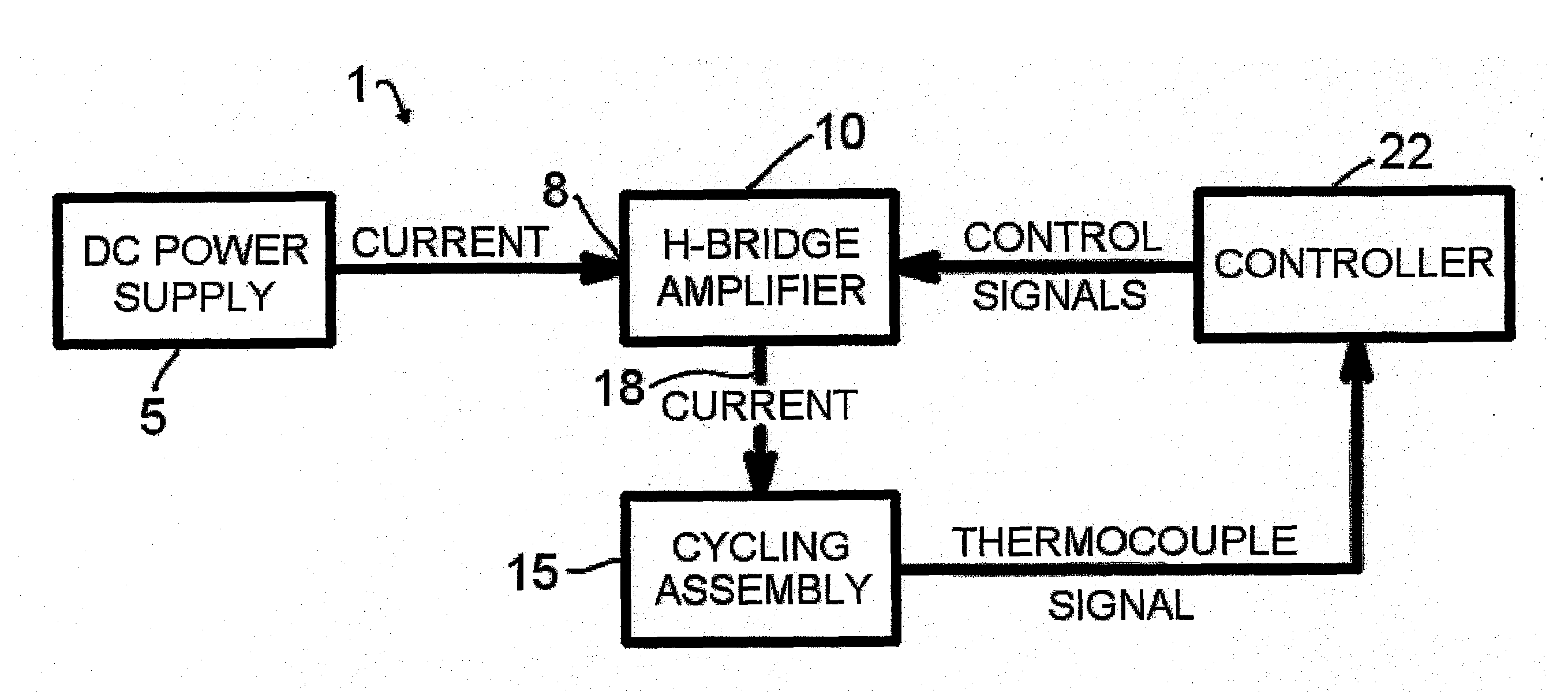
[0044]A representative diagram of the major components of the thermocycler apparatus 1 of the present invention for conducting rapid thermocycling on any number of biological samples is shown in FIG. 1. A
direct current power supply 5 with appropriate specifications is electrically connected to the power input 8 of an H-bridge
electronic circuit 10. The lead wires of the thermoelectric modules within the cycling
assembly 15 are connected to the
power output 18 of the H-
bridge circuit 10. One or multiple
temperature measurement devices, such as but not limited to thermocouples, are present in the
assembly 15 and provide information to a controller 22, which in turn controls the behavior (for example, electrical power and directionality) of the H-bridge 10. In embodiments of the invention, the thermocouples may be located in a sample vessel, a sample vessel holder, a module laminate, or combinations thereof. The controller 22 is programmable by the user and may be operated via a multiplicity of computer-controlled operations. Various techniques well known in the art of
control theory, such as PID control, can be utilized to subject the samples to PCR temperature protocols specified by the user. In embodiments of the invention where two or more pairs of thermoelectric modules are employed, the controller may control the pairs of thermoelectric modules so that the modules run independent temperature protocols simultaneously, or the same temperature protocols simultaneously.
[0045]The use of thermoelectric devices (Peltier effect) for heating and cooling applications is well known in the art. Conventional, commercially available thermoelectric devices or Peltier devices may be employed in the apparatus and methods of the present invention. These Peltier devices are generally comprised of
electron-doped n-p
semiconductor pairs that act as miniature heat pumps. When current is applied to the
semiconductor pairs, a
temperature difference is established whereas one side becomes hot and the other cold. If the current direction is reversed, the hot and cold faces will be reversed. Usually an electrically nonconductive material layer, such as aluminum
nitride or
polyimide, comprises the substrate faces of the thermoelectric modules so as to allow for proper isolation of the
semiconductor element arrays. In a preferred embodiment of the present invention, the opposing thermoelectric modules are spatially oriented such that when
positive current is applied, both interior faces become hot and heat the sample vessels. When the current direction is reversed via the H-bridge, both of the interior faces become cold, and the sample vessels are cooled. Alternatively, it is facile to see that the wiring of the modules or apparatus
electronics could be modified to produce the same heating and cooling effects.
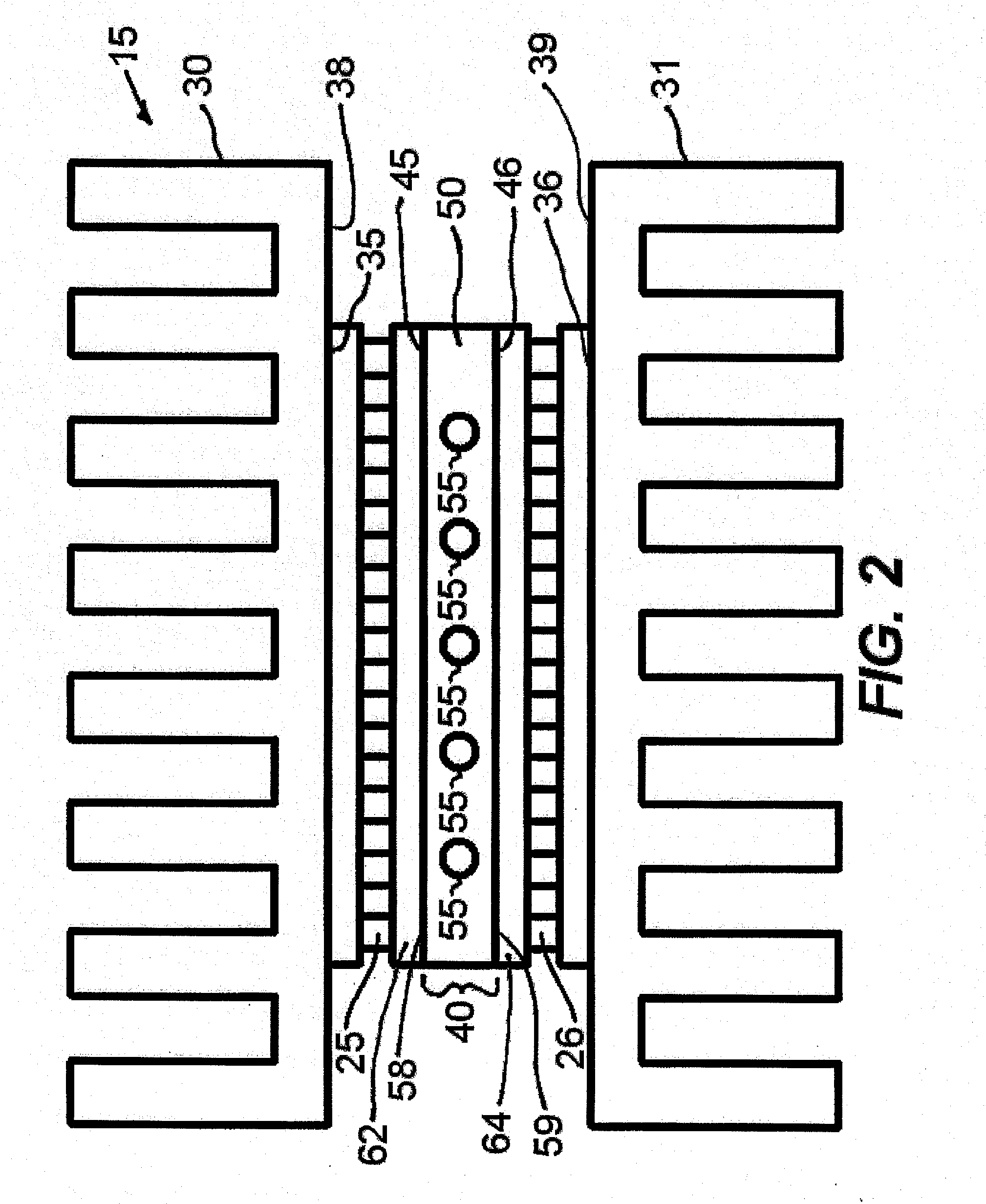
[0046]An example of a cycling
assembly 15 is shown in FIG. 2. The Peltier devices or thermoelectric modules 25 and 26 are placed in substantial spatial opposition to one another. In preferred embodiments the opposing thermoelectric modules are oriented at least substantially vertically with their major opposing heat transfer surfaces being vertically oriented and at least substantially parallel to each other. Heat sinks 30 and 31 may be placed in
thermal contact with the exterior faces 35 and 36, respectively of the thermoelectric modules 25 and 26, respectively to dissipate heat and allow for good heat pumping efficiency of the thermoelectric modules 25, 26. The heat sinks 30, 31 are designed as well known in the art of
heat exchanger design, and are generally made of
copper or aluminum. Generally, the
heat sink inner surface 38, 39 will be larger than the
mating outer face 35, 36 respectively of the thermoelectric module 25, 26, respectively. In the region 40 between the interior faces 45 and 46 of the thermoelectric modules 25, 26, respectively, a machined material or sample holder 50 is present such that sample vessels may be inserted into the open areas of the machined material 50. This material has a high
thermal conductivity but low thermal
mass, such as but not limited to aluminum or silver, to facilitate rapid heat transfer and temperature uniformity. To facilitate good contact among the heat sinks 30, 31, thermoelectric modules 25, 26, and machined interior
metal 50,
heat sink compound or thermal paste may be applied to
mating surfaces. Additionally, one or more fans (not shown) may be present to aid in heat dissipation from the heat sinks through either unidirectional or impingement methods. The interior material 50, in FIG. 2 has one or more holes, passageways, or cavities 55 fabricated in it that are toleranced such that a close fit is obtained when capillaries are inserted. Similarly, the holes 55 could take on an oval shape to accommodate oval glass or plastic capillaries to allow for larger reaction volumes. The outer walls or outer surfaces 58, 59 of the interior material or sample holder 50 are in direct contact with the interior faces 45 and 46 of the thermoelectric modules 25, 26, respectively for efficient, rapid heat transfer between the sample holder 50 and samples contained therein 55 and the thermoelectric modules 25, 26. Alternatively, sample holder 50 and the inner opposing substrates 62, 64 of thermoelectric modules 25, 26, respectively could be made of one
solid surface with high
thermal conductivity but low electrical
conductivity and low thermal
mass, such as but not limited to bare or metallized ceramics.
[0047]As shown in FIG. 3, a slotted version of the cycling assembly 115 is another embodiment of the present invention. In this embodiment and applicable to other embodiments of the present invention, the thermoelectric modules 125 and 126 are placed in substantial spatial opposition to one another, but have heat sinks 130 and 131, respectively, integrated into the outer substrate 135, 136, respectively of the thermoelectric modules 125, 126, respectively. In other words, the outer substrates 135, 136 of the thermoelectric modules 125, 126 are fabricated into the form of heat sinks 130, 131 before bonding to the Peltier arrays 125, 126. Similarly, the inner substrate or sample vessel holder 150 is shared by both thermoelectric modules 125 and 126 upon fabrication. This results in a rather compact and integrated cycling assembly 115. In the interior cavity or slot 155 of the inner substrate 150, sample vessels are inserted such that a substantial portion of the vessel walls comes into good
thermal contact or direct contact with the interior or cavity walls 160 of the slot 155 of thermoelectric modules 125, 126 to allow for rapid thermocycling. In embodiments of the invention, the inner substrate 150 may have a plurality of slots arranged along the central longitudinal axis of the inner substrate 150 for simultaneously accommodating a plurality of sample vessels.
[0048]FIG. 4 illustrates a hinged embodiment of a cycling assembly 215 of the present invention. As in the previously described embodiments of FIGS. 2 and 3, the hinged cycling assembly 215 has thermoelectric modules 225 and 226 and heat sinks 230 and 231. In this embodiment, a hinge mechanism 270 and latch mechanism 275 may be utilized. The hinge 270 is hingedly attached to an end of the heat sinks 230 and 231 and enables opening of the interior space 280 between the thermoelectric modules 225 and 226 to allow for facile
insertion of sample vessels into the interior space 280, especially substantially deformable or “thin-disk” vessels. The latch mechanism 275 includes a latch 276 attached to
heat sink 230 and a ledge or protrusion 277 attached to heat sink 231. The protrusion 277 is engaged by latch 276 when the hinge 270 is closed to keep the heat sinks 230 and 231 in a
fixed position. When the hinge 270 is closed and latch mechanism 275 engaged, substantial portions of the sample vessels come into good
thermal contact or direct contact with the inner substrates 285, 290 of the thermoelectric modules 225 and 226, respectively, to enable rapid thermocycling. Alternatively, the hinge mechanism 270 could be detachable with one or more latch mechanism 275 and latch 276 to keep the heat sinks 230 and 231, and thermoelectric modules 225 and 226, in a
fixed position when latched.

