This helps you quickly interpret patents by identifying the three key elements:
Problems solved by technology
Method used
Benefits of technology
Benefits of technology
[0009]According to an embodiment of the present invention, amorphous semiconductor including hydrogen is used as an electrolyte of a redox capacitor. As the amorphous semiconductor including hydrogen, amorphous silicon, amorphous silicon germanium, or amorphous germanium can be used. As the amorphous semiconductor including hydrogen, oxide semiconductor including hydrogen can be used. As typical examples of the oxide semiconductor including hydrogen, zinc oxide, titanium oxide, nickel oxide, vanadium oxide, and indium oxide can be given. As the amorphous semiconductor including hydrogen, an In—M—Zn-oxide semiconductor (M is one or more metal elements selected from Al, Ga, Fe, Ni, Mn, and Co) can be used. A crystal of InMO3(ZnO)m (m>0) may be included in the amorphous structure. Further, nitrogen may be included in the In—M—Zn-oxide semiconductor. When nitrogen is included, the hydrogen concentration in the In—M—Zn-oxide semiconductor can be increased.
[0011]By employing an embodiment of the present invention, a redox capacitor which can operate at room temperature and has a simple structure can be manufactured.
In addition, in the case of using cesium hydrogensulfate as an electrolyte of the redox capacitor, cesium hydrogensulfate needs to be used at a temperature higher than or equal to about 143° C.: structural phase transition of cesium hydrogensulfate occurs at about 143° C. Meanwhile, for the usage at room temperature, moisture is necessary; thus, the redox capacitor needs to be used in an atmosphere in which the humidity is increased, which causes a problem of increase in size of the redox capacitor.
Method used
Image
Click on the blue label to locate the original text in one second.
Reading with bidirectional positioning of images and text.
Examples
embodiment 1
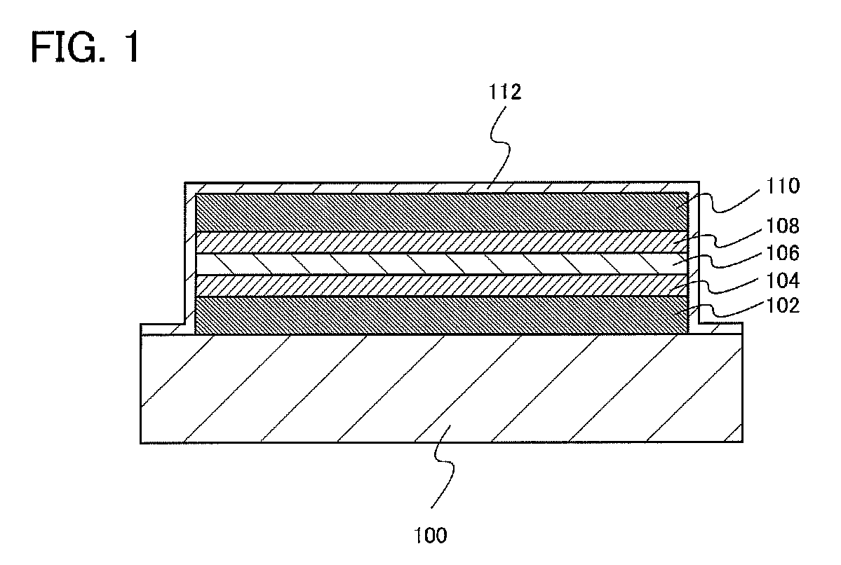
[0021]In this embodiment, an embodiment of a redox capacitor structure will be described with reference to FIG. 1.
[0022]Over a substrate 100, a first current collector 102, a first active material 104 formed over the first current collector 102, an electrolyte 106 formed over the first active material 104, a second active material 108 formed over the electrolyte 106, and a second current collector 110 formed over the second active material 108 are included.
[0023]For the substrate 100, glass, quartz, ceramic such as alumina or plastic can be used. As the plastic, a fiberglass-reinforced plastics (FRP) plate, a polyvinyl fluoride (PVF) film, a polyester film, or an acrylic resin film can be used.
[0024]One of the first current collector 102 and the second current collector 110 functions as a positive electrode current collector, and the other functions as a negative electrode current collector. As the first current collector 102 and the second current collector 110, an element such as ...
embodiment 2
[0039]In this embodiment, a structure of a redox capacitor, which is different from the structure in Embodiment 1, will be described with reference to FIGS. 3A and 3B.
[0040]A redox capacitor illustrated in FIG. 3A includes an electrolyte 126 formed over a substrate 120, a first active material 124 and a second active material 128 which are formed over the electrolyte 126, a first current collector 122 formed over the first active material 124, and a second current collector 130 formed over the second active material 128.
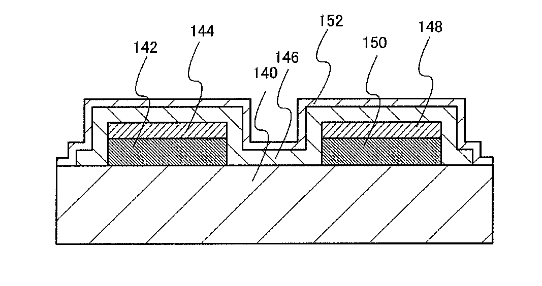
[0041]The redox capacitor illustrated in FIG. 3B includes a first current collector 142 and a second current collector 150 which are formed over a substrate 140, a first active material 144 formed over the first current collector 142, a second active material 148 formed over the second current collector 150, and an electrolyte 146 which covers side surfaces of the first current collector 142 and the second current collector 150 and top surfaces and side surfaces of t...
embodiment 3
[0050]In this embodiment, redox capacitors capable of increasing the capacitance more than those of Embodiments 1 and 2 will be described with reference to FIGS. 5A to 5C. The redox capacitors described in this embodiment is characterized in that a first current collector or an electrolyte formed over a substrate has a projection and depression shape.
[0051]The redox capacitor illustrated in FIG. 5A includes a first current collector 162 having a projection and depression shape formed over a substrate 160, a first active material 164 formed over the first current collector 162, an electrolyte 166 formed over the first active material 164, a second active material 168 formed over the electrolyte 166, and a second current collector 170 formed over the second active material 168.
[0052]The redox capacitor illustrated in FIG. 5B includes an electrolyte 186 having a projection and depression shape formed over a substrate 180, a first active material 184 and a second active material 188 whi...
TECHNICAL FIELD[0001]The present invention relates to a redoxcapacitor and a manufacturing method thereof.BACKGROUND ART[0002]Electrochemical capacitors have been developed in recent years. The electrochemical capacitors include, in its category, an electric double-layer capacitor (EDLC) that utilizes capacitance formed by electrostatically storing positive and negative charges at interfaces between electrodes and an electrolytic solution, and a redox capacitor that utilizes capacitance that is stored along an electron transfer process (Faraday process) on an electrode surface.[0003]As an electrolyte of the redox capacitor, an acid aqueous solution such as sulfuric acid or hydrochloric acid, cesium hydrogensulfate, or the like is used (see Patent Document 1 and Patent Document 2).[0004][Reference][0005][Patent Document 1] Japanese Published Patent Application No. 2003-109875[0006][Patent Document 2] Japanese Published Patent Application No. 2007-123833DISCLOSURE OF INVENTION[0007]H...
Claims
Application Information
Patent Timeline
Application Date:The date an application was filed.
Publication Date:The date a patent or application was officially published.
First Publication Date:The earliest publication date of a patent with the same application number.
Issue Date:Publication date of the patent grant document.
PCT Entry Date:The Entry date of PCT National Phase.
Estimated Expiry Date:The statutory expiry date of a patent right according to the Patent Law, and it is the longest term of protection that the patent right can achieve without the termination of the patent right due to other reasons(Term extension factor has been taken into account ).
Invalid Date:Actual expiry date is based on effective date or publication date of legal transaction data of invalid patent.

