Integrated Process and System for Steam Cracking and Catalytic Hydrovisbreaking with Catalyst Recycle

Inactive Publication Date: 2011-07-28
EXXONMOBIL CHEM PAT INC
View PDF18 Cites 8 Cited by
  • Summary
  • Abstract
  • Description
  • Claims
  • Application Information

AI Technical Summary

Benefits of technology

[0049]In a preferred embodiment, wherein the feed comprises crude or atmospheric resid that contain appreciable amounts of 1050° F.+ (566° C.+) resids, e.g., 10 wt % or more of resid, or 20 wt % or more of resid, or even up to 50 wt % of resid, the resid-containing feed may be passed into the convection section of a pyrolysis unit, where it is heated and mixed with superheated steam. Then the heated mixture may be passed to a knockout drum (or pressure reduction device), which is integrated with the pyrolysis unit, to drop out the heaviest fraction (e.g., substantially all of the asphaltenes). The terms “knockout drum” and knockout pot” are used interchangeably herein; they are known in the art, meaning generally, a vessel or system to separate a liquid phase from a vapor phase. The term “flash” means generally to effect a phase change for at least a portion of the material in the vessel from liquid to vapor, via a reduction in pressure and/or an increase in temperature. Thus the terms “flash drum” and “flash pot” indicate a vessel where phase change for at least a portion of the material in the vessel from liquid to vapor occurs. The addition of steam well upstream of the knockout drum, required for steam cracking, will reduce the hydrocarbon partial pressure, which effects vaporization of the 750° F.+ (399° C.) to 1050° F.+ (566° C.+) (preferably even a substantial portion of the 1100° F.+ (593° C.+)) resid fractions, and prevent fouling.
[0050]Preferred knockout drums or vapor liquid separation devices, and their integration with pyrolysis units have previously been described in U.S. Patent Application Publication Nos. 2004/0004022, 2004/0004027, and 2004/0004028, which are incorporated herein by reference. Another apparatus effective as a flash pot for purposes of the present invention is described in U.S. Pat. No. 6,632,351 as a “vapor/liquid separator”.
[0051]The knockout drum preferably operates at a temperature of between about 800° F. (about 425° C.) and about 870° F. (about 465° C.), but also typically not over about 900° F. (about 482° C.). Separating material through the knockout drum to obtain an overhead vapor and liquid bottoms further facilitates vaporization of the 650° F.+ (343° C.+) resids.
[0052]Steam cracking alone provides for a product comprising significant yields of fuel oil, tar, and non-aromatic SCN (steam cracked naphtha) in addition to the desired ethylene, propylene, butylenes, C5 olefins and dienes, cycl

Problems solved by technology

However, conventional steam cracking processes are known to be prone to severe fouling by feedstocks containing even small concentrations of resid, which is commonly present in low quality, heavy feeds.
Thus, most steam cracking furnaces are limited to processing of higher quality feedstocks which have had the resid fraction re

Method used


Image

  • Integrated Process and System for Steam Cracking and Catalytic Hydrovisbreaking with Catalyst Recycle
  • Integrated Process and System for Steam Cracking and Catalytic Hydrovisbreaking with Catalyst Recycle

Examples


Example

Example 1

[0064]Catalytic hydrovisbreaking lab tests were conducted using Cold Lake vacuum residual oil in autoclave reactors for 180 seconds at 870° F. (465.6° C.). Results are summarized in Table 1. It can be seen that catalytic hydrovisbreaking provided improved CCR conversion and greatly reduced coke as compared to visbreaking and hydrovisbreaking without catalysts.

TABLE 1Treat Gas(1300 psig N2H2H2(8963 kPa-gauge))(visbreaking)(CHVB)(hydrovisbreaking)Catalyst load (ppmw)01000975° F.+ (523.9° C.+) 3548.148conversion %CCR conversion %generates 10%15generates 2%Coke wt %Coil coked0.151.7

Example

Example 2

[0065]Related experiments were carried out using higher catalyst concentrations at a lower temperature of 775° F. (413° C.) and for 120 minutes using arab light vacuum resid. Table 2 below illustrates representative results. Higher catalyst concentrations improved metals removal, CCR conversion and increased saturates production.

TABLE 21050° F.+ conversion5053Catalyst load (wt %)0.62.4Demetallization %6596CCR conversion %3346Increase in saturates %1215

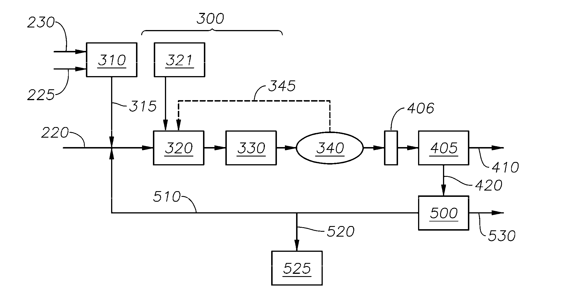
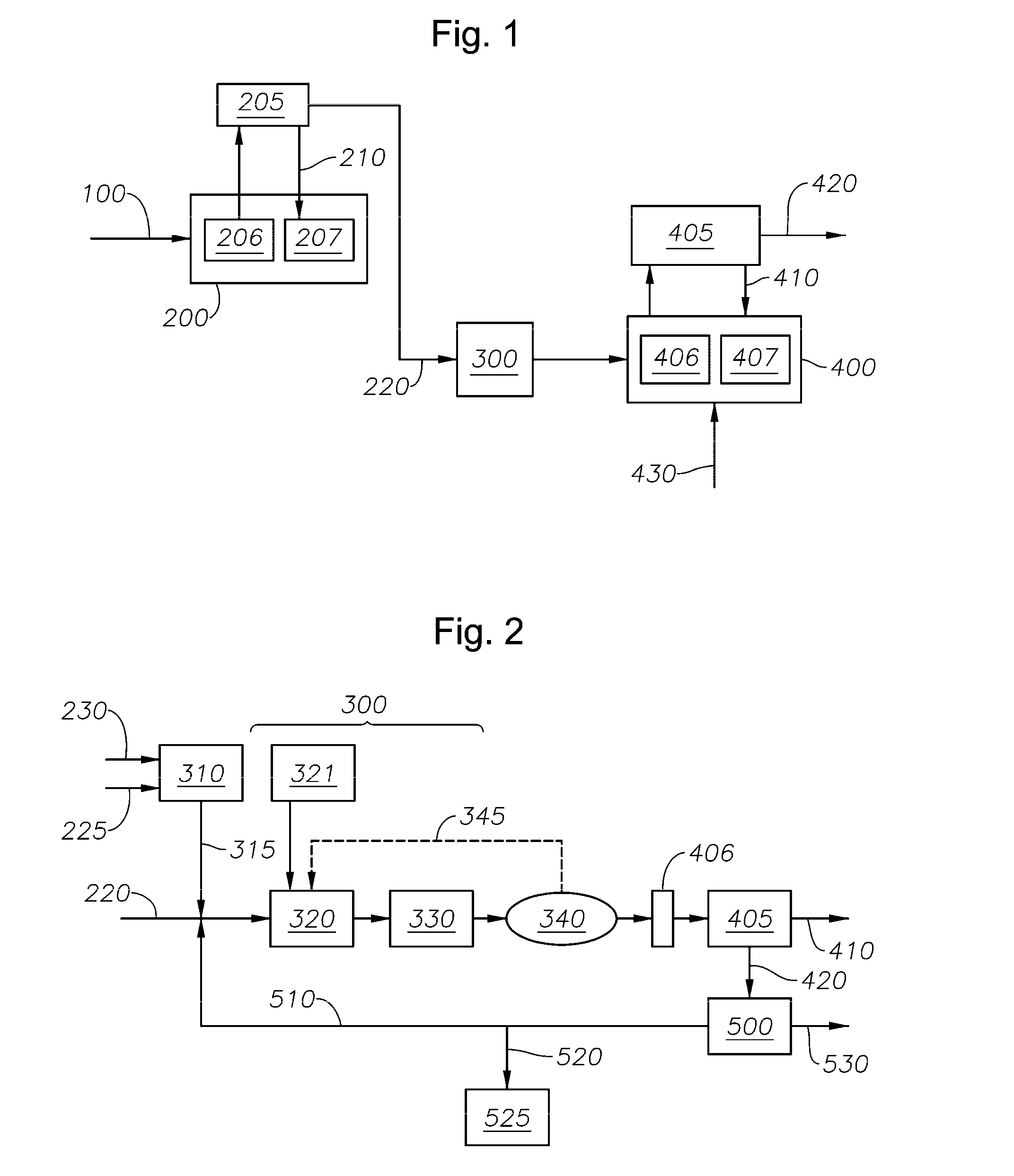
[0066]While vacuum resid catalytic hydrovisbreaking is known for fuels processing, the integration of CHVB with a steam cracking furnace including an integrated knockout drum is not known. Moreover, use of CHVB processes with high catalyst concentrations and catalyst recycle is not well known. Those skilled in the art of heavy feed processing are familiar with the difficulties of operating heavy feed steam cracking and coking processes without fouling. It is not obvious how to integrate the processes without further aggravatin...


PUM


Abstract

This invention relates to a process for cracking hydrocarbon feedstock containing resid comprising:
    • (a) heating a hydrocarbon feedstock containing resid;
    • (b) adding molecular hydrogen to said heated feedstock to form a mixture stream;
    • (c) adding a catalyst containing metal-sulfide particles to said heated feedstock and/or said mixture stream;
    • (d) reacting said mixture in a catalytic hydrovisbreaking reactor under conditions of temperature, pressure and residence time sufficient to catalytically hydrovisbreak at least a portion of said resid into hydrovisbroken hydrocarbon components;
    • (e) passing said reacted mixture stream into a high pressure separator and separating hydrogen from said reacted mixture;
    • (f) passing said reacted mixture through a knockout drum to remove catalyst and unreacted or uncracked resid as a bottoms stream; and
    • (g) passing said catalytically hydrovisbroken hydrocarbon components into a steam cracking furnace and thermally cracking said hydrocarbon components to form light olefins, alternately the knockout drum of step (f) is integrated into the steam cracking furnace of step (g).

Description

FIELD OF THE INVENTION[0001]The invention relates to a method of making olefins from a crude or resid-containing crude fraction.BACKGROUND OF THE INVENTION[0002]Thermal cracking of hydrocarbons is a petrochemical process that is widely used to produce olefins such as ethylene, propylene, butylenes, butadiene; aromatics such as benzene, toluene, and xylenes; and hydrogen. Each of these is a valuable commercial product in its own right. For instance, the olefins may be oligomerized (e.g., to form lubricant basestocks), polymerized (e.g., to form polyethylene, polypropylene, and other plastics), and / or functionalized (e.g., to form acids, alcohols, aldehydes and the like), all of which have well-known intermediate and / or end uses. One thermal cracking process is steam cracking, which involves cracking hydrocarbons in the presence of steam or steam-containing gases.[0003]Typically in steam cracking, a hydrocarbon feedstock for steam cracking, such as naphtha, gas oil, or other non-resid...

Claims


Application Information

Patent Timeline
IPC IPC(8): C10G65/10B01J8/00
CPCC10G45/60C10G2300/302C10G69/06C10G47/06
Inventor DAVIS, STEPHEN MARKKEUSENKOTHEN, PAUL F.MCCONNACHIE, JONATHAN MARTINIACCINO, LARRY L.STELL, RICHARD C.
Owner EXXONMOBIL CHEM PAT INC
Why Eureka
Try Eureka