Method of manufacturing hydrophilic membrane having improved antifouling property and hydrophilic membrane manufactured by the method

a hydrophilic membrane and anti-fouling technology, which is applied in the direction of filtration separation, pretreatment surfaces, separation processes, etc., can solve the problems of rapid decrease of permeation flux, adsorption of membrane pores and membrane pores, and adsorption of membrane pores and closing of membrane pores, etc., to achieve excellent hydrophobic membrane properties such as thermal stability, chemical stability and mechanical strength, and low protein adsorption. , the effect of high permeation flux

Inactive Publication Date: 2011-10-20
KOREA INST OF SCI & TECH
View PDF13 Cites 37 Cited by
  • Summary
  • Abstract
  • Description
  • Claims
  • Application Information

AI Technical Summary

Benefits of technology

[0020]According to the present invention, hydrophilicization can be introduced to the surfaces and micropores of the membranes permanently by uniformly coating micropores as well as surfaces of the hydrophobic membranes with the dissolved solution after dissolving a hydrophilic monomer into a supercritical fluid or a subcritical fluid and contacting the dissolved solution with hydrophobic membranes. A membrane manufactured by the present invention is excellent in properties of a hydrophobic membrane such as thermal stability, chemical stability and mechanical strength,

Problems solved by technology

Membrane fouling is characterized in that concentrates or excluded components such as proteins, cells, colloids and others dispersed or dissolved in a solution are adsorbed onto surface and micropores of the membranes, which results in a sharp decline of the permeation flux in the course of permeation period.
The membrane fouling is caused by external fouling in which the excluded components are adsorbed onto the membrane surfaces to form a gel layer, a cake layer, a scale layer and other layers, and internal fouling causing adsorption of membrane pores and closure of the membrane pores.
If such surface and micropores of the membranes are fouled, there is a problem that the permeation flux is rapidly decreased or properties of the membranes are varied with the passage of time to result in a deteriorating separation function of the membranes.
However, in conclusion, the method results in deteriorating economic efficiency of the membrane process since much of energy is consumed due to frequent cleaning, a constant permeation flux cannot be obtained, and the membranes should be replaced due to impossible performance recovery of the membranes.
The cellulose-based membranes have drawbacks that the cellulose-based polymers are very sensitive to heat, chemical resistance of the cellulose-based polymers is low, and main chains of the cellulose-based polymers are easily cleaved by enzyme and the like, although the cellulose-based polymers have characteristics that water is easily penetrated through the cellulose-based membranes by the interaction between water and the cellulose-based membranes such as hydrogen bonds and the like.
However, the polyamide-based polymers have drawbacks that it is difficult to manufacture polyamide-based polymers for microfiltration membranes or ultrafiltration membranes, and the polyamide-based polymers are strongly bonded with proteins to result in a severe fouling of the membranes.
However, the hydrophobic membranes have a drawback that a high trans-membrane pressure should be applied to allow water penetration through the hydrophobic membranes because there are no chemical functional groups that are capable of obtaining good interaction between water and the membrane such as hydrogen bonds and the like such that the hydrophobic membranes are not easily wetted by water.
Furthermore, the hydrophobic membranes have a drawback that the hydrophobic membranes are extremely sensitive to membrane fouling compared to the hydrophilic polymer membranes.
The physical coating method has a drawback that it is difficult to coat the internal micropores of the membranes uniformly because of the high surface tension and the high viscosity of coating solvents, typically water.
In addition, high expenses are often required for post-treatment of the used coating solvents.
Moreover, the physical

Method used


Image

  • Method of manufacturing hydrophilic membrane having improved antifouling property and hydrophilic membrane manufactured by the method
  • Method of manufacturing hydrophilic membrane having improved antifouling property and hydrophilic membrane manufactured by the method
  • Method of manufacturing hydrophilic membrane having improved antifouling property and hydrophilic membrane manufactured by the method

Examples


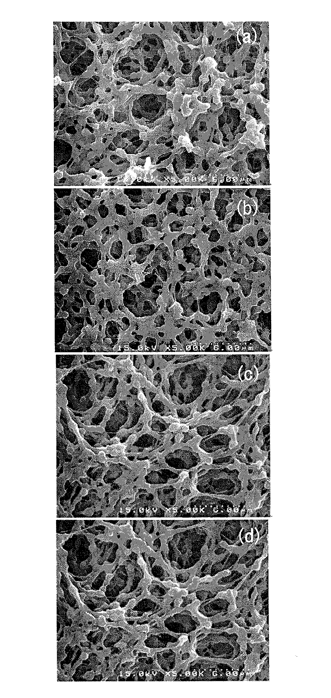
example 2 and example 3

, Example 2 and Example 3;

[0026]FIG. 5 illustrates permeation results obtained when penetrating a solution containing 1,000 mg / L of BSA into a PDVF MF membrane hydrophilicized after cleaning; and

[0027]FIG. 6 shows protein adsorption characteristics of the PDVF MF membrane contaminated after penetrating a solution containing 1,000 mg / L of BSA into a PDVF MF membrane hydrophilicized after cleaning.

EXPLANATION OF REFERENCE NUMERALS FOR MAIN PORTIONS IN DRAWINGS

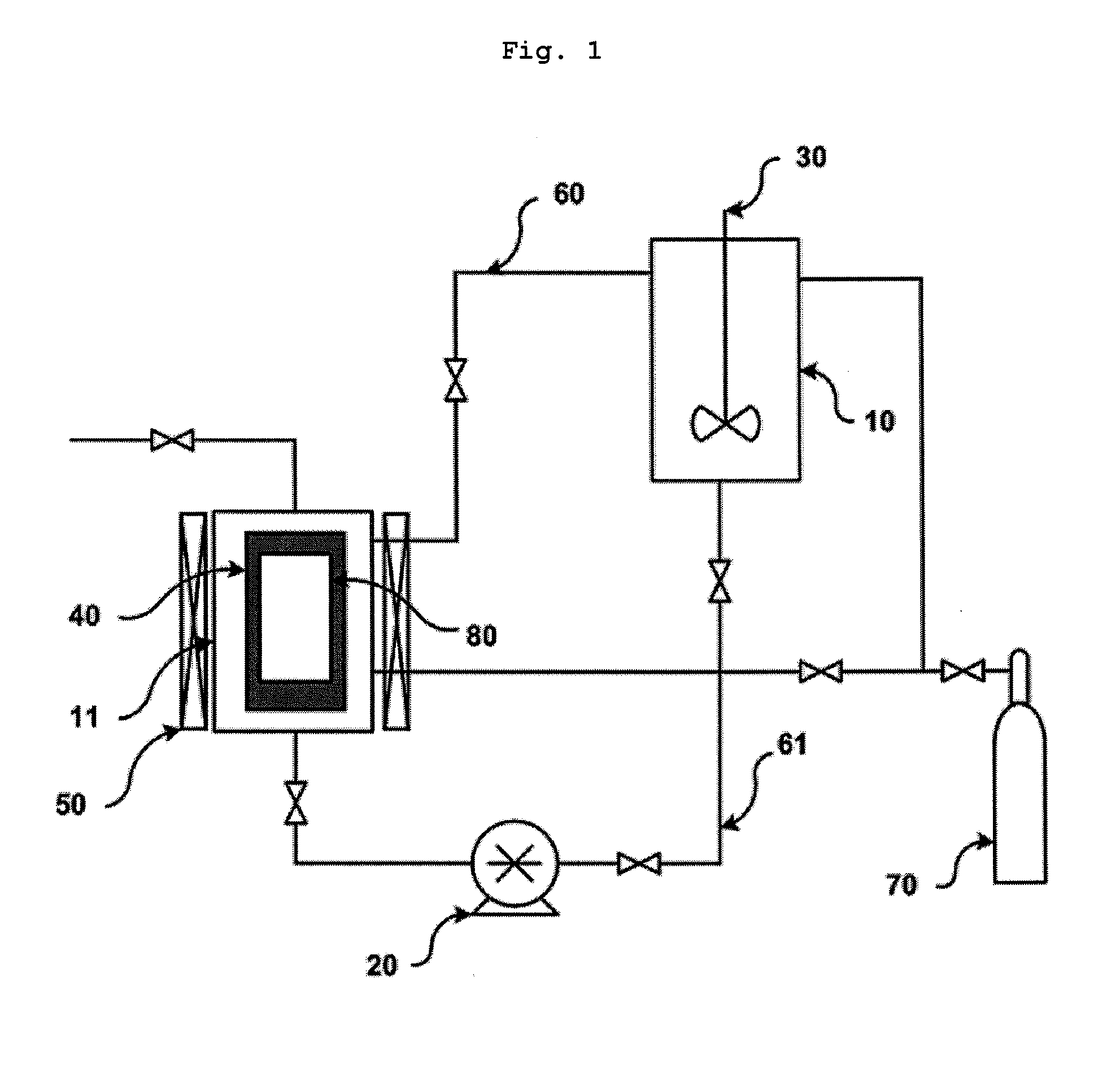
[0028]10: High pressure solution vessel[0029]11: High pressure coating vessel[0030]20: High pressure pump[0031]30: High pressure magnetic stirrer[0032]40: Internal heater[0033]50: External heater[0034]60: Gas passage line[0035]61: Solution transfer line[0036]70: Supercritical fluid or subcritical fluid vessel[0037]80: Membrane

DESCRIPTION OF THE PREFERRED EMBODIMENTS

[0038]Features and advantages of the present invention will be more clearly understood by the following detailed description of the present preferred embodiments by re...

example 1

[0069]1 g of polyethylene glycol diacrylate (PEGDA, Mn of 575 g / mol) containing a hydrophilic functional group and a cross-linking reaction-enabling group was introduced into a high pressure solution vessel of 1500 ml of which a temperature was controlled to 15° C., and 0.03 g of 2,2′-azobis(2-methylpropionitrile) (AIBN) as an initiator was introduced into the high pressure solution vessel. 1200 ml of liquid carbon dioxide was introduced into the high pressure solution vessel to adjust the monomer concentration to 0.1% by weight, and a pressure of the vessel was controlled to 50 bars. The solution was stirred for 2 hours by a high pressure magnetic stirrer to prepare a uniform coating solution. After adjusting a polyvinylidene difluoride (PVDF) MF membrane having an average pore size of 0.45 μm and a thickness of about 30 μm to a size of 20×10 cm2 and fixing the size-adjusted PVDF MF membrane to an internal heater having a size of 21×11 cm2 installed in a high pressure coating vesse...

example 2

[0070]A hydrophilicized PVDF MF membrane was manufactured by the same method as in the Example 1 except that 4.95 g instead of 1 g of polyethylene glycol diacrylate (PEGDA, Mn of 575 g / mol) containing a hydrophilic functional group and a cross-linking reaction-enabling group was used, and 0.16 g instead of 0.03 g of 2,2′-azobis(2-methylpropionitrile) (AIBN) as an initiator was used.


PUM

PropertyMeasurementUnit
Temperatureaaaaaaaaaa

Abstract

A method of manufacturing a hydrophilic membrane and hydrophilic membranes having improved antifouling property using a supercritical fluid or a subcritical fluid. The method involves combining a coating solution from a hydrophilic group-containing monomer, an initiator, a cross-linking agent and a supercritical fluid or subcritical fluid in a high pressure solution vessel and transferring the coating solution to a membrane in a high pressure coating vessel, coating the surfaces and micropores of the membranes through cross-linking polymerization reactions. Non-reacted coating material is returned to the high pressure solution vessel. The membranes are removed from the coating vessel, cleaned and dried. The hydrophilic membrane manufactured by the present invention is excellent in properties of hydrophobic membranes such as thermal stability, chemical stability and mechanical strength, and surfaces and micropores of the membranes are uniformly coated.

Description

CROSS-REFERENCES TO RELATED APPLICATION[0001]This patent application claims the benefit of priority from Korean Patent Application No. 10-2010-0035417, filed on Apr. 16, 2010, the contents of which are incorporated herein by reference.BACKGROUND OF THE INVENTION[0002]1. Field of the Invention[0003]The present invention relates to a method of manufacturing a hydrophilic membrane having improved antifouling property and the hydrophilic membrane manufactured by the method.[0004]2. Description of the Related Art[0005]A process based on membranes is an energy saving type process which is not accompanied by phase, temperature and pressure changes that are inevitably accompanied in most separation processes, wherein importance of the process is greatly being magnified by combining the process of using membranes with various separation devices and developing materials for the membranes such that the process has recently been utilized in various fields including seawater desalination, food p...

Claims


Application Information

Patent Timeline
IPC IPC(8): B01D71/06B01D71/50B05D3/10B01D71/34B01D71/32B01D71/64B01D71/68
CPCB01D65/08B01D67/0006B01D71/26B01D71/34B01D71/36B01D2321/16B01D71/64B01D71/68B01D2323/225B01D2323/30B01D2325/36B01D71/50
Inventor KIM, JAEHOONLEE, YOUNG HAENGKIM, JAE-DUCKPARK, JONG MINJURNG, JONGSOO
Owner KOREA INST OF SCI & TECH
Why Eureka
Try Eureka