[0019]According to the first form of the present invention, because average particle diameter D of said metallic catalyst particles is within a range of 0.5 nm≦D≦80 nm, and individual particle size d of said metallic catalyst particles is within the range of said average particle diameter D, it can effect a highly efficient growth of a brush-like carbon nanostructure comprising brush-like CNTs by said metallic catalyst particles. Here, said average particle diameter D is the arithmetic mean of all the particles that are observed in a selected square division of 100 nm-10 μm side length. When the number of all said particles is taken as n, and the diameter of an individual particle is taken as di (i=1,2, . . . , n), then average particle diameter D is expressed as D=(d1+d2+ . . . +n) / n. Said metallic catalyst particles contain a metallic element that acts as a catalyst, that is to say, a catalyst
metal as the main component; it is preferable to contain an
oxide of the catalyst
metal, and a suitable catalyst performance is imparted. When said average particle diameter D is less than 0.5 nm, most of said metallic catalyst particles will have the diameter equal to or less than that of a CNT, and the capability as a catalyst for growing CNTs is lost. In addition, when said average particle diameter D exceeds 80 nm, most of said metallic catalyst particles become larger than the diameter of a CNT, and the number of the metallic catalyst particles for growing CNTs is reduced considerably. Therefore, by said average particle diameter D and,said individual particle size d being in said range, brush-like CNTs with uniform CNT diameters can be: produced with high efficiency. In addition, the catalyst body concerning the present invention is constituted from the part that is composed of a catalyst material, and from other members (substrate, reaction preventive layer). As for the configuration of the substrate, there are various forms, such as a substrate; a multilayer substrate, a
pipe body, a polyhedron, a pellet, and a
powder. According to the catalyst body for production of brush-shaped carbon nanostructure concerning the present invention, brush-like CNTs from which rope-like CNTs can be produced, whose CNTs are oriented in
high density, can be produced in a large quantity, cheaply, and stably.
[0020]In addition, because the catalyst body for production of brush-shaped carbon nanostructure comprises the substrate, the reaction preventive layer that has been formed on said
substrate surface, and the catalyst layer on said reaction preventive layer, said reaction preventive layer has an extremely
low affinity with said catalyst
metal, and therefore during the temperature increasing process at the time of said CNT synthesis, the substrate and the metallic catalyst particles can be prevented from reacting, and the catalyst function of said metallic catalyst particles can be maintained. Said reaction preventive layer is formed from an
oxide or a
heat resistant resin whose reactivity with the catalyst metal is extremely low, and even if the catalyst body for production of brush-shaped carbon nanostructure concerning the present invention is
heat treated with a high temperature, said catalyst metal can prevent a bonding with the substrate materials. More specifically, a reaction preventive layer such as
silicon carbide,
silicon oxide, aluminum oxide,
magnesium oxide,
titanium oxide, and
zirconium oxide is formed. As for said catalyst metal, it can be chosen appropriately from iron,
tin,
indium,
cobalt,
nickel, their alloys, or their oxides, and when metallic catalyst particles in which any of the above catalyst metals is contained as the main component are formed, the reaction of the metallic catalyst particles with the substrate by the heat treatment can be prevented by the reaction preventive layer. For example, in the case in which said metallic catalyst particle comprises one or more types of
iron oxide, brush-like CNTs in which the CNTs are densely packed are formed, and in the case in which they include, aside from
iron oxide, one or more types of oxide of a selection from
tin,
indium,
cobalt,
nickel, and their alloys, it is possible to grow coil-like CNTs, or in other words, carbon nanocoils. Therefore, by choosing accordingly the constituent element and the composition of the metallic catalyst particle, along with the manufacture condition, various kinds of brush-like carbon nanostruetures can be produced.
[0021]According to the second form of the present invention, because ratio ΔD / D of said half
band width ΔD with respect to said average particle diameter D is within a range of 0<ΔD / D≦0.7, by said average particle diameter D being set within a range of 0.5 nm≦D≦80 nm, individual particle size d of said metallic catalyst particle is set to a suitable size for the growth of CNTs, and uniformized at the same time, and therefore uniform brush-like CNTs can be grown with high efficiency. In said
particle size distribution, said half
band width ΔD is within a range of 0<ΔD / D≦0.7 with respect to average particle diameter D, said particle size d is clustered at the vicinity of said average particle diameter D, the uniformity of said metallic catalyst particles is maintained, and therefore brush-like
carbon nanostructures of, among others, brush-like CNTs can be grown with high efficiency, and a high uniformity is realized particularly with brush-like CNTs. When said ratio ΔD / D exceeds 0.7, because the
particle size distribution widens, the diameters of the growing brush-like CNTs become uneven, and it becomes difficult to make rope-like CNTs, and furthermore, it becomes impossible to produce rope-like CNTs whose predetermined diameter is maintained throughout the full length. Furthermore, the number per unit area, of said metallic catalyst particles forming said catalyst layer is equal to or more than 1×10⁸ / cm2, and because metallic catalyst particles of the particle size which allows the growth of CNTs are formed uniformly as described above, uniform brush-like CNTs of
high density can be produced with high efficiency. It has been confirmed that the production of rope-like CNTs is virtually impossible for the case in which the CNT density of the brush-like CNTs is less than 1×10⁸ / cm2, and as described above, it is required that the density of said metallic catalyst particle is equal to or more than 1×10⁸ / cm2, at least. Considering that it is difficult to make CNTs grow, from all metallic catalyst particles, it is more preferable that the number per unit area'of said metallic catalyst particle is equal to or more than 1×10⁹ / cm2.
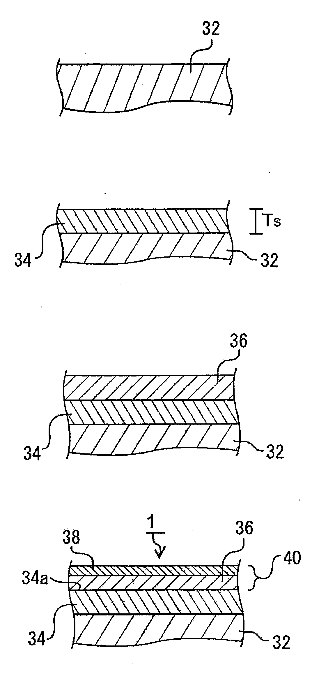
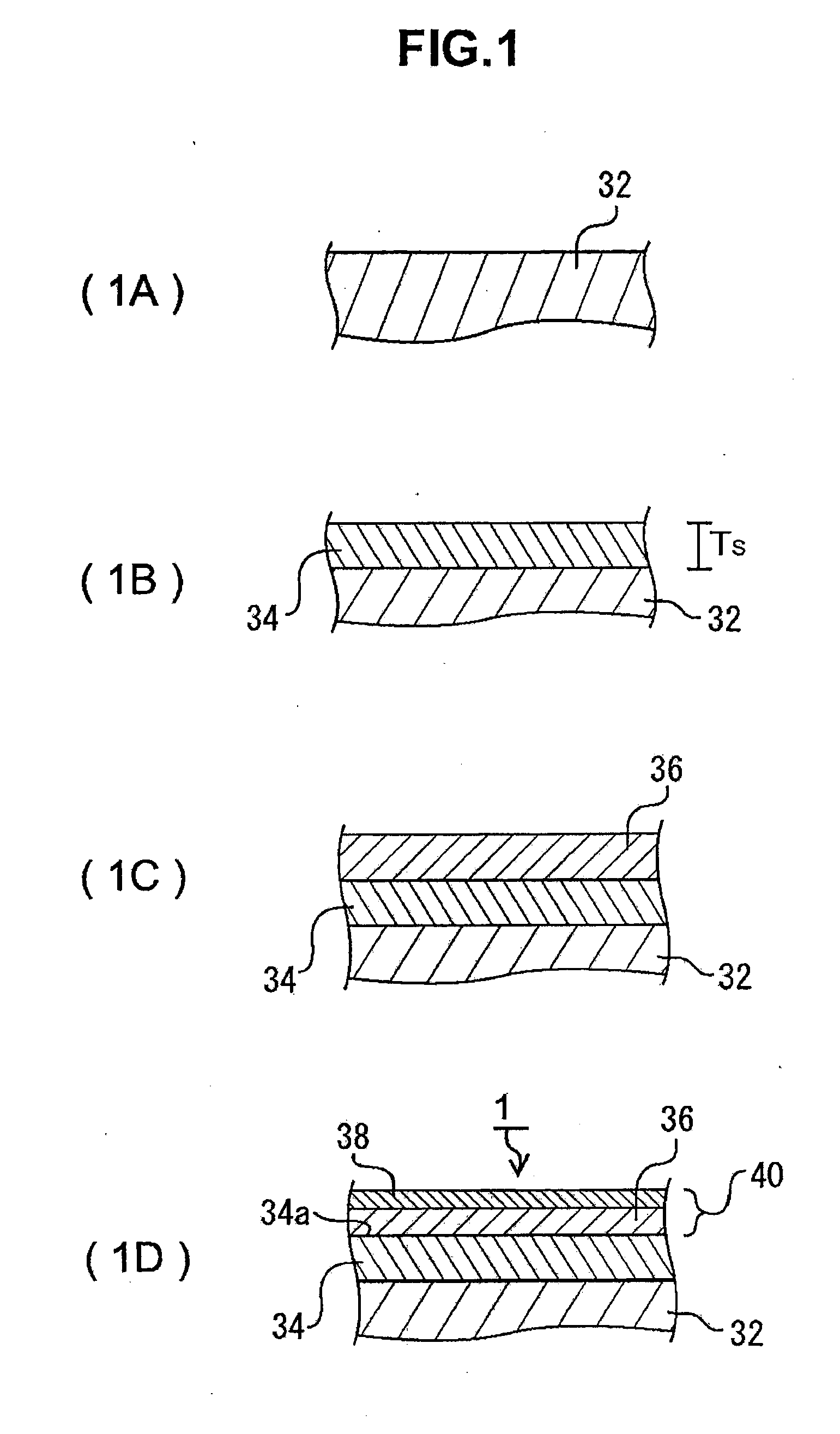
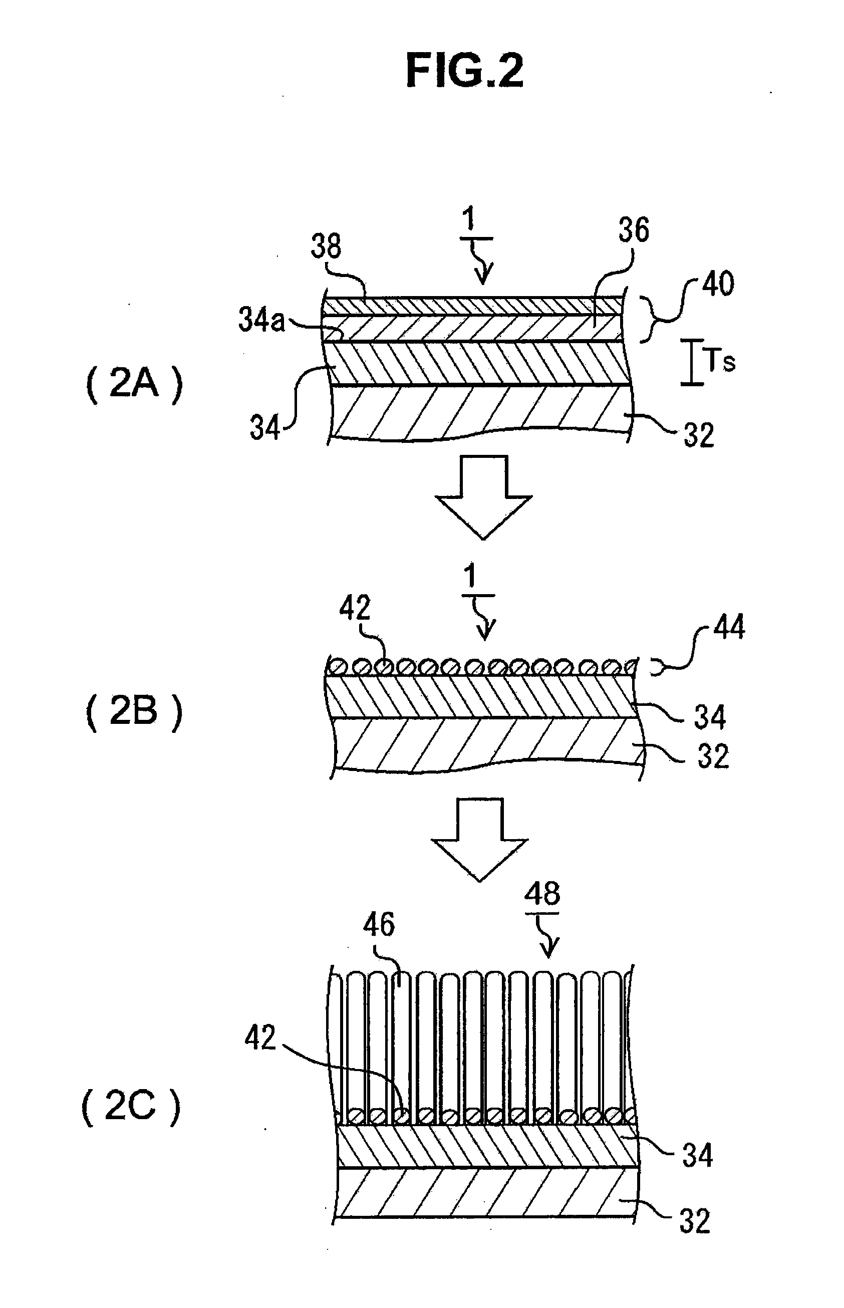
[0022]According to the third form of the present invention, because said catalyst layer comprises the catalyst metal layer on said reaction preventive layer and the aggregation suppressive layer which has been formed on the surface of said catalyst metal layer, when brush-like CNTs are grown by heat treatment, it can suppress the aggregation of the metallic catalyst particles which were formed by
granulation of the catalyst metal layer, and the enlargement greater than the given particle size suitable for the growth of CNTs. Said catalyst layer of the third form is a precursor to the catalyst particle layer, and by the heat treatment fox synthesizing CNTs, the catalyst particle layer is formed from said catalyst layer. Said aggregation suppressive layer is formed by oxides of said catalyst metal layer, and it is preferable for it to have a
melting point higher than that of said catalyst metal layer. As an aside, because the fluidity starting temperature of the metal lowers from that of the bulk metal when the thickness of said catalyst metal layer is equal to or less than a few to a few tens of nm, it is sufficient that the fluidity starting temperature of said aggregation suppressive layer is set higher than the lowered fluidity starting temperature of the catalyst metal layer. In addition, in said aggregation suppressive layer, said catalyst metal layer can suppress the oxidation during the
granulation process, and the oxidized metal composition within said metallic catalyst particles can be set to a suitable quantity. For example, When said substrate is a
silicon substrate, an oxidized silicon layer can be formed as said reaction preventive layer by heating the
substrate surface, and said reaction preventive layer can be formed comparatively easily. In this case, the reaction of said catalyst metal with the substrate and the subsequent formation of
metal silicide are prevented. As an aside, said silicon substrate allows for the formation of a flat surface of high precision, and at the same time, can be produced cheaply, and therefore it is a preferable material as the substrate material.
[0023]According to the fourth form of the present invention, said aggregation suppressive layer comprises metal oxides of the metallic element composing said catalyst metal layer, and the aggregation suppressive layer can be formed comparatively easily by applying an oxidation treatment on the surface of said catalyst metal layer. In addition, when said aggregation suppressive layer is formed by the
physical vapor deposition method or the
chemical vapor deposition method, the affinity with the catalyst metal layer is good, and said aggregation suppressive layer can formed with higher efficiency. The metal oxide forming the aggregation suppressive layer concerning the present invention has a high
melting point than that of the catalyst metal layer. Therefore, as described above, in the growth process of the brush-like CNTs in which heat treatment is applied, it can suppress the aggregation of said granulated catalyst metal layer by surface fusion and the enlargement greater than the given particle size suitable for the growth of CNTs. In addition, said aggregation suppressive layer, in said heat treatment process and at the time of the formation of said catalyst particle layer, can prevent an excessive oxidation of said catalyst metal. More specifically, when said catalyst metal layer is formed from iron,
tin,
indium,
cobalt, or
nickel, said aggregation suppressive layer is formed, respectively, by FeO, Fe2O3, Fe3O4, SnO2, CoO, or NiO.
[0024]According to the fifth form of the present invention, because the thickness of said reaction preventive layer is equal to or greater than 10 nm, the reaction between said catalyst layer and said substrate can be prevented more securely. When the thickness of said reaction preventive layer is less than 10 nm, there is a possibility that the substrate materials diffuse to said reaction preventive layer by the heat treatment, causing a reaction with said catalyst metal. The present inventors have performed an examination on the effect of the reaction preventive layer at the growth temperature of CNTs, and confirmed that when the thickness of said reaction preventive layer is equal to or greater than 10 nm, the reaction between said catalyst layer and said substrate is definitely prevented. Thickness of said reaction preventive layer can be set appropriately according to the purpose of the brush-like CNTs, the substrate structure, and others, as long as said thickness is equal to or more than 10 nm.

