Power converter with linear distribution of heat sources

a technology of power converters and heat sources, applied in the direction of lighting and heating apparatus, electric apparatus casings/cabinets/drawers, instruments, etc., can solve the problems of affecting the cost, performance and reliability of any power converter, generating heat by the semiconductor device, etc., to improve performance, enhance reliability, and reduce costs

Inactive Publication Date: 2012-02-02
PARKER INTANGIBLES LLC
View PDF10 Cites 15 Cited by
  • Summary
  • Abstract
  • Description
  • Claims
  • Application Information

AI Technical Summary

Benefits of technology

[0006]The invention is a power converter of any circuit topology that contains power semiconductor components, magnetic power components and capacitors where a novel means of thermal management is used to substantially improve performance, enhance reliability and reduce costs.
[0007]The primary utility of the invention is in DC-to-AC power converters used in large solar photovoltaic power plants. Prior art central inverters for large solar power plants all use forced convection or liquid cooling methods requiring “moving” parts. These inverters typically have a usable lifetime of about fifteen years or half that of the connected solar photovoltaic modules. A power converter based on the natural convection cooled embodiment of the invention can achieve inverter/module lifetime parity. By using the disclosed linear distribution of heat sources, component operating temperatures can be kept much lower per unit cost of heatsink material. Sufficiently low operating temperatures extend component lifetimes and enable the use of internal solid potting materials in order to mitigate condensation, corrosion and particulate contamination. With low operating temp...

Problems solved by technology

All power components generate waste heat in the power conversion process.
Semiconductor devices generate heat due to conducti...

Method used


Image

  • Power converter with linear distribution of heat sources
  • Power converter with linear distribution of heat sources
  • Power converter with linear distribution of heat sources

Examples


Embodiment Construction

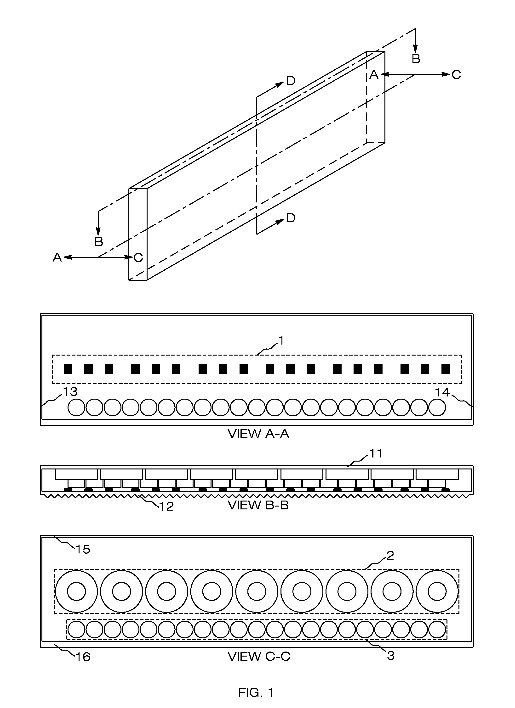
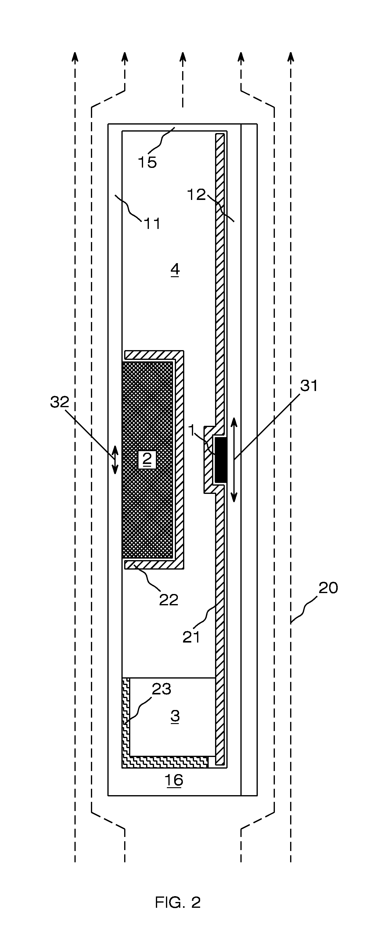
[0013]A power converter design using discrete semiconductors and flat-form magnetic components will be described. This low power design is optimized for natural convection cooling. A high power design will next be described which uses semiconductor power modules and forced convection cooling. In both cases it will be demonstrated that with the invention, significant improvements can achieved in power converter performance and with a substantial reduction in power component costs.

[0014]FIG. 1 illustrates the preferred embodiment of the invention as a DC to 3-phase AC power converter or inverter. The power converter is housed in a six sided enclosure comprising front panel 11, rear panel 12, top panel 15, bottom panel 16, and side panels 13 and 14. All panels, or sides of the enclosure, act as heatsinks for internal electrical components to transfer heat to ambient air outside of the enclosure. The power converter illustrated is optimized for natural convection but may also be used wi...


PUM


Abstract

A power converter design is disclosed with a novel approach to thermal management which enhances the performance and significantly reduces the cost of the converter compared to prior art power converters. The invention minimizes the heating of one power component by another within the power converter and therefore enables the power converter to work at higher power levels. Essentially, the power converter uses a heatsink having a high length to width ratio, a linear array of power components thermally coupled to the heatsink parallel to the long axis of the heatsink and a heat removal system which produces the highest cross sectional thermal flux perpendicular to said long axis. In addition, a number of ancillary thermal management techniques are used to significantly enhance the value of this basic approach. A specific circuit design for the power converter is not disclosed or discussed as the invention can be applied to any number of power converter electrical topologies. What is addressed is the specific thermal management of the three primary component groups found in any power converter; semiconductor devices, magnetic components and capacitors. The invention uses specific geometries and power component arrangements as well as strategic use of advanced thermal materials.

Description

BACKGROUND OF THE INVENTION[0001]Power converters for renewable energy power conversion, motor drives and uninterruptible power systems (UPS) all use three basic power component types; semiconductor devices, magnet components and capacitors. All power components generate waste heat in the power conversion process.[0002]Semiconductor devices generate heat due to conduction, switching and diode recovery losses. The waste heat must be transferred out of the device to limit the semiconductor die temperatures to safe maximums. Semiconductors are typically the primary source of power converter waste heat.[0003]Magnetic components such as transformers and filter inductors have copper and core losses that generate heat, heat which must be removed to maintain the core properties and to protect the integrity of the electrical insulating materials.[0004]Power capacitors used across a DC buss or as AC filters also generate heat from ripple currents acting against the internal impedance of a cap...

Claims


Application Information

Patent Timeline
IPC IPC(8): H05K7/20H02M7/537
CPCH02M7/003H05K7/20945H05K7/209
Inventor WEST, RICHARD TRAVIS
Owner PARKER INTANGIBLES LLC
Why Eureka
Try Eureka