
Portable high gain fluorescence detection system

a fluorescence detection and high gain technology, applied in the field of compact fluorescence detection instruments, can solve the problems of less effective conventional confocal localization of excitation and emission signals in generating robust signals over a wide range of sample and operating conditions, and achieve the effects of reducing the need for precision, improving the manufacturability of the apparatus, and high amplification gain

Active Publication Date: 2012-05-10
PERKINELMER HEALTH SCIENCES INC
View PDF4 Cites 65 Cited by
  • Summary
  • Abstract
  • Description
  • Claims
  • Application Information

AI Technical Summary

Benefits of technology

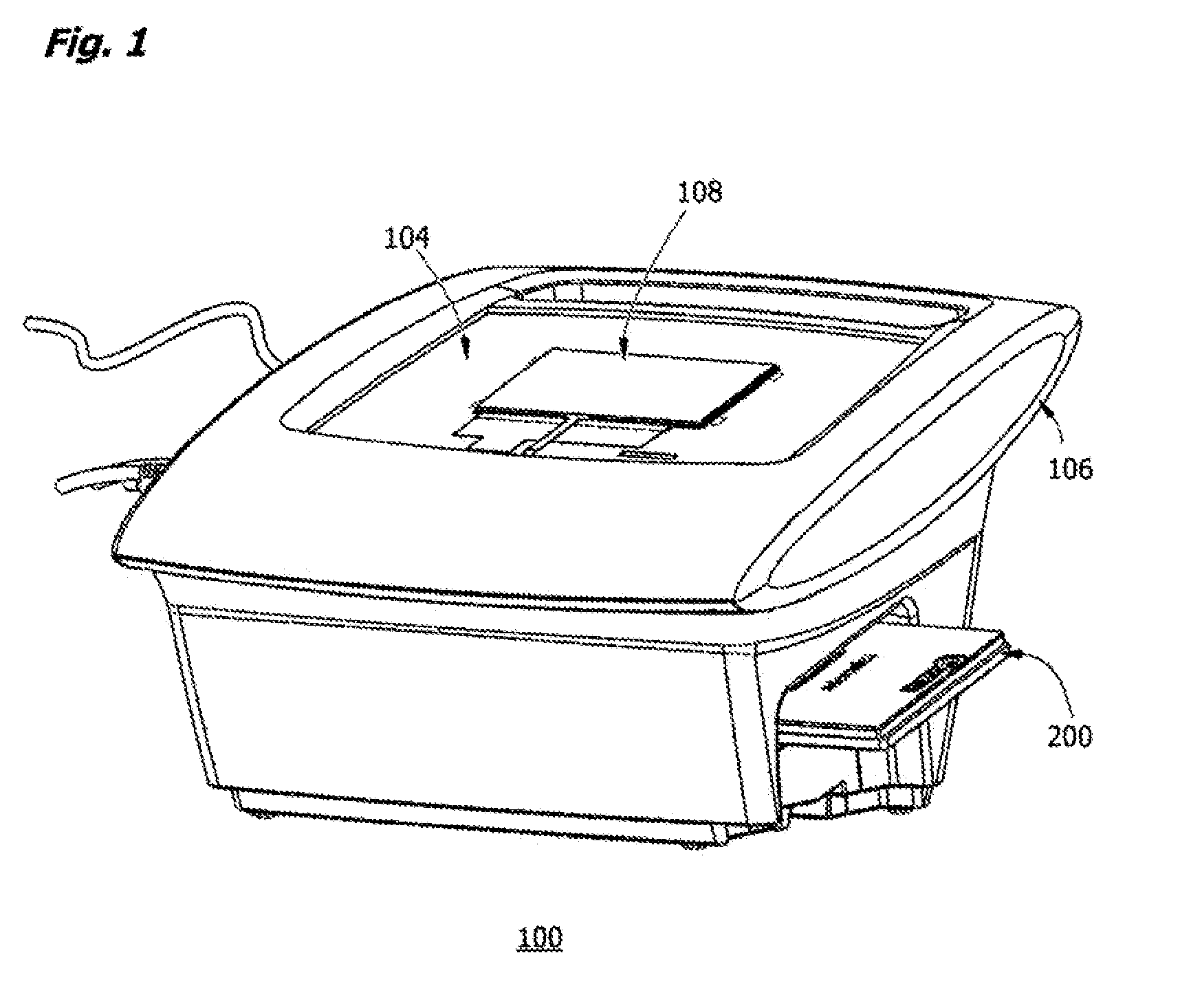
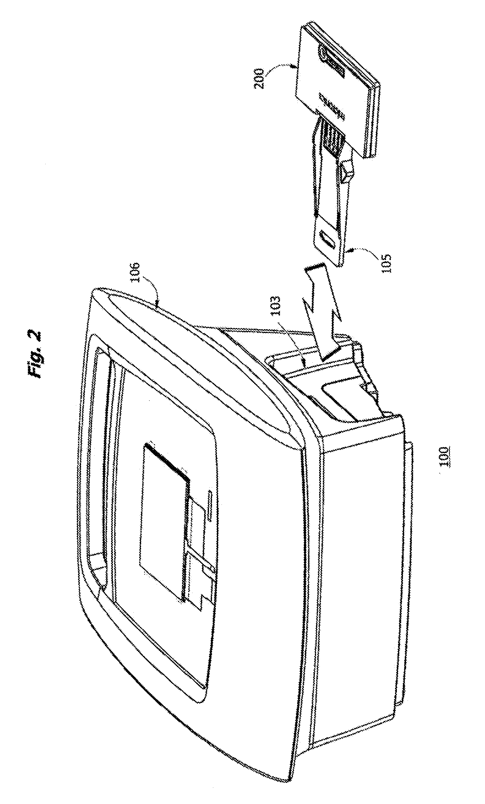
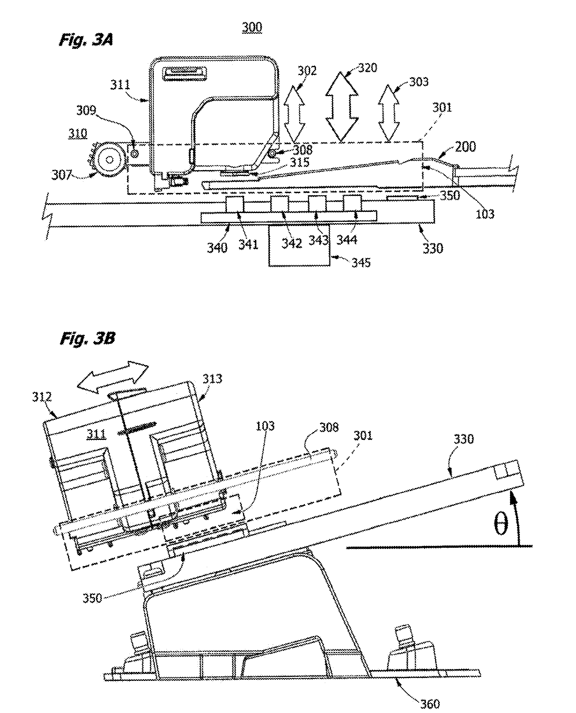
[0016]The present invention addresses the problem of reliable and sensitive detection of fluorescent probes, tags, fluorophores and analytes in a microfluidic cartridge in the presence of bubbles and other interfering inhomogeneities in a liquid sample, in a first aspect of the invention, by providing a reflective mirror face formed on a heating block that contactingly interfaces with a thermo-optical window on the underside of the detection channel or chamber containing the liquid sample. The mirror face is formed on the top surface of a heating block and contacts the lower optical window of the detection chamber during use, avoiding the complexity and expense of manufacturing an integral mirror on the bottom of each disposable cartridge, and allowing us to use thinner, more compliant films with lower resistance to heat transfer and transparent optical characteristics for the thermo-optical window of the cartridge. The mirror face is optically flat and polished to improve both heat transfer and fluorescence emission capture. A scanning objective lens is positioned above an upper optical window on the top of the microfluidic cartridge. Excitation light is transmitted through both the upper optical window and the lower thermo-optical window before striking the mirror and reflecting back. Direct and reflected emissions are collected by the objective lens and focused on a detection sensor such as a photodiode, photocell, photovoltaic device, CMOS or CCD chip.
[0018]Contrary to the teachings of the prior art, we find that the conventional confocal localization of the excitation and emission signal is less effective in generating a robust signal over a wide range of sample and operating conditions. Therefore, in one aspect of the invention, it was found that optimization of signal detection may be improved by displacement of the focal point of the excitation light from the plane of the sample to a point behind the sample, a technological advance in the field of low cost optics for use with microfluidic fluorescence assays. Decoupling of excitation and emission optics flies against decades of prior art dedicated to the principles (first espoused by Minsky in U.S. Pat. No. 3,013,467) that form the foundation of conventional practice in confocal microscopy, epifluorescence detection, and microfluidic fluorescence assays. The prior art teachings have lead to the use of aspherical lenses, laser diodes, and precise parfocal alignment of the detection optics with the excitation optics. In contrast, the optics required for delocalized focus of the excitation cone as described here are fortuitously of very low cost and do not require precision assembly or maintenance, as is desirable for manufacturing a low cost, portable instrument.

Problems solved by technology

Contrary to the teachings of the prior art, we find that the conventional confocal localization of the excitation and emission signal is less effective in generating a robust signal over a wide range of sample and operating conditions.

Method used


Image

  • Portable high gain fluorescence detection system
  • Portable high gain fluorescence detection system
  • Portable high gain fluorescence detection system

Examples


example i

[0159]In this example, the apparatus of the invention is shown to be useful in diagnosis of infectious disease by detection of the nucleic acids of a pathogen in a human sample such as blood. Using on-board dry and liquid reagents, a blood sample is processed and DNA associated with Plasmodium falciparum is detected in about 30 minutes or less. DNA purified from the sample is subjected to PCR using two microfluidic chambers with dual temperature zones as described in U.S. Pat. No. 7,544,506 and U.S. patent application Ser. No. 11 / 562,611 (Microfluidic Mixing and Analytical Apparatus), which are coassigned. Amplicon is then detected using a FAM fluorescence-tagged molecular beacon directed at the amplified target. Optionally, a control consisting of a California Red-tagged RNAaseP leukocyte exon sequence, with multiplex amplification, is used to validate the assay. A representative thermal melt curve obtained using the thermo-optical interface of the invention is shown in FIG. 22A.

example ii

[0160]The apparatus of the invention is useful in the diagnosis of coagulopathies. Using on-board dry and liquid reagents, a blood sample is assayed for Coagulation Factor VIIa deficiency by incubating plasma with a fluorogenic substrate such as (D-Phe-Pro-Arg-ANSNH-cyclohexyl-2HCl; F.W.=777.81, Haematologic Technologies, Essex Junction, Vt.) where ANSN is fluorophore 6-amino-1-naphthalene-sulfonamide, which lights up when the amide bond between the dye and the peptide is cleaved. Tissue Factor (TF) is obtained from Calbiochem (LaJolla Calif.) and incorporated into phosphatidylcholine or phosphatidylserine vesicles before use. TF is used in excess. A 100 uL substrate reaction mixture consisting of 20 mM Hepes buffer, pH 7.4, 0.15 M NaCl, with 5 nM TF and containing 20 uM EDTA is incubated with a plasma sample for 10 min to form the active enzyme complex. The ANSH substrate is then added. The rate of hydrolysis of substrate is linear over the normal range of Factor VIIa, and can be d...


PUM

PropertyMeasurementUnit
angleaaaaaaaaaa
angleaaaaaaaaaa
angleaaaaaaaaaa

Abstract

An instrument for fluorometric assays in liquid samples is disclosed. The instrument may include multiple optical channels for monitoring a first fluorophore associated with a target analyte and a second fluorophore associated with a control. The disclosed instrument finds utility in any number of applications, including microfluidic molecular biological assays based on PCR amplification of target nucleic acids and fluorometric assays in general.

Description

CROSS-REFERENCE TO RELATED APPLICATIONS[0001]This application is a continuation of application Ser. No. 13 / 191,120, which was filed on Jul. 26, 2011, now pending, which is a continuation of International PCT Patent Application No. PCT / US2010 / 022581, which was filed on Jan. 29, 2010, now pending, which claims the benefit under 35 U.S.C. §119(e) of U.S. Provisional Patent Application No. 61 / 148,843, filed Jan. 30, 2009, which applications are incorporated herein by reference in their entireties.BACKGROUND[0002]1. Field[0003]The present invention relates to a compact fluorescence detection instrument with optics for use in assays performed in a microfluidic cartridge.[0004]2. Description of the Related Art[0005]Although the benefits of the use of fluorophores as probes for in-vitro diagnostic assays are well known, the most commonly available forms of equipment for such assays are large, complex to use, relatively slow and rely on expensive confocal optics. These attributes make much e...

Claims


Application Information

Patent Timeline
Patent Type & Authority Applications(United States)
IPC IPC(8): C12M1/34G01N21/64
CPCG01N21/645G01N21/6452G01N2201/0245G01N21/6456C12M23/16G01N21/6454B01L7/52
Inventor BATTRELL, C. FREDERICKDAIBER, TROY D.
Owner PERKINELMER HEALTH SCIENCES INC
Learn More